Heavy lift engineering essentials every lift engineer should know
2026-06-12
Heavy lift engineering is where structural design, rigging, marine operations, fabrication planning and approval management meet. For a lift engineer, the task is not simply to confirm that a crane can pick up a load. The real task is to prove that the complete lifting system can be executed safely, within the limitations of the vessel, structure, equipment, weather window and approval process.
That system view matters because heavy lift projects usually run under high schedule pressure. A late padeye redesign, unclear centre of gravity, missing underdeck check or incomplete MWS package can delay mobilisation, increase fabrication hours and create offshore risk. Good heavy lift engineering reduces uncertainty before the hook moves.
The essentials below apply across offshore wind, shipbuilding, vessel retrofit, decommissioning, dredging, traditional energy and heavy civil marine work. They are practical fundamentals every lift engineer should control before a lift plan becomes an offshore operation.
Why heavy lift engineering needs a system view
A heavy lift is a temporary condition, but it can govern the entire project. Structures that are safe in service may experience their highest stresses during lifting, transport, upending, tailing, skidding or set-down. Temporary structures such as grillages, spreader beams, lifting frames, seafastening and deck reinforcement can become just as critical as the permanent asset.
This is why heavy lift engineering must connect multiple disciplines. Structural engineers need to understand load paths and local stresses. Naval architects need to understand vessel behaviour, stability, ballast and motions. Operations teams need procedures that can be followed safely on deck. Fabricators need details that are realistic to build, inspect and deliver on time. Review parties need documents that are complete enough to approve without repeated clarification cycles.
A lift engineer adds value by keeping these interfaces aligned. The strongest calculation is not useful if the rigging cannot be installed, the welds cannot be inspected, the crane radius is not achievable or the documentation does not satisfy the marine warranty surveyor.
Start with a controlled lift basis
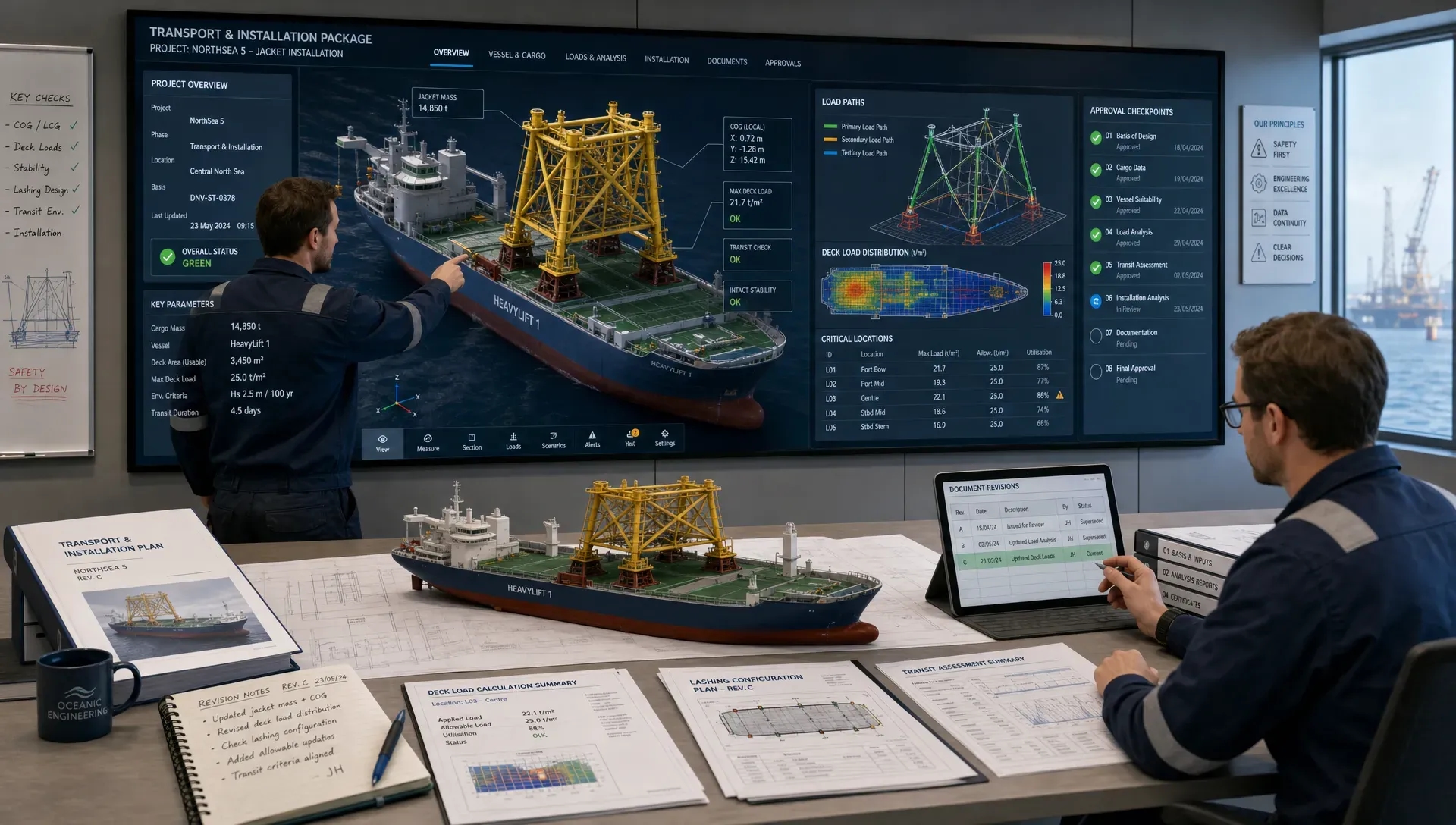
Every safe lift starts with a controlled design basis. This should define what is being lifted, how it is being lifted, what assumptions are used and which acceptance criteria govern the work. Without this foundation, later calculations may look precise while still being based on uncertain data.
A lift engineer should be especially careful with weight and centre of gravity information. Certified weight reports, weighing results, vendor data and 3D model take-offs must be reviewed for scope gaps. Temporary items such as rigging, access platforms, sea fastening remnants, fluids, insulation, piping contents or lifting tools can be missed if the boundary is unclear.
A good lift basis normally defines:
- The gross lifted weight, weight contingency and the source of weight data.
- The centre of gravity coordinates, tolerance and possible as-built deviation.
- The lift configuration, including crane radius, hook height, rigging geometry and pick points.
- The governing load cases, including dynamic effects, skew load, wind, vessel motions and accidental or contingency cases where required.
- The applicable standards, client specifications, class rules and marine warranty requirements.
- The required deliverables, review sequence, approval parties and hold points.
Common reference frameworks may include DNV-ST-N001 for marine operations, DNV-ST-N002 for sea transport, relevant class society rules, Eurocode or AISC checks, ASME B30 or LOLER requirements where applicable, and project-specific specifications. Not every project uses the same framework, so the lift basis must be agreed early rather than assumed.
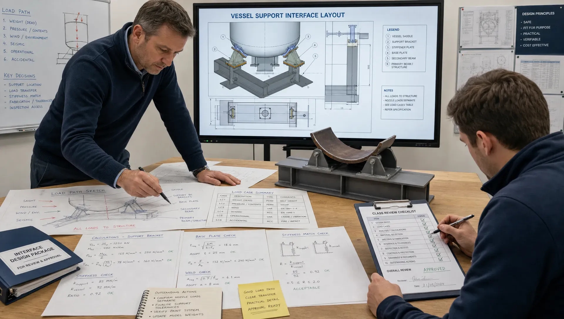
Follow the real load path
Heavy lift failures often start with an incomplete understanding of the load path. The path begins at the hook and continues through the block, slings, shackles, spreader bars, lifting trunnions or padeyes, local structure, global module frame, grillage, vessel deck and underdeck reinforcement. Each transition introduces eccentricities, local bending, contact effects, weld demands and possible tolerance issues.
For a lift engineer, following the load path means checking more than the main member utilisation. Local details often govern. A padeye cheek plate may pass in bearing, but the surrounding web may fail in out-of-plane bending. A trunnion may have adequate section capacity, but the load introduction into the shell or frame may require reinforcement. A deck grillage may be strong enough globally, but the supporting deck beams may not accept the point load without underdeck strengthening.
Finite element analysis is powerful for these checks, especially where load paths are three-dimensional or where local stress concentrations matter. However, FEM should not replace engineering judgement. Boundary conditions, mesh strategy, contact assumptions and load application need to reflect the real operation. A model that is clean but unrealistic can produce confident results for the wrong problem.
Treat rigging geometry as a design driver
Rigging geometry controls force distribution. Small changes in sling angle, pick point elevation, shackle orientation or centre of gravity position can change sling tensions and lift point reactions significantly. This is one reason a lift engineer should avoid treating rigging as a procurement item that can be finalised after the structural checks.
If a sling angle is measured from the vertical, sling tension increases as the angle becomes larger because the vertical component of the tension reduces. If the angle is measured from the horizontal, the interpretation is different. This simple convention mismatch can lead to serious errors, so all drawings, calculations and rigging documents must define angles clearly.
Load sharing also deserves attention. Four-point lifts are often assumed to share load evenly, but real distribution depends on stiffness, sling lengths, tolerances, geometry and CoG offset. Spreader beams, equalising systems and controlled sling adjustment can help, but they must be represented properly in the design model and procedure.
Shackles and hooks also have practical limits. Side loading, insufficient articulation, wrong pin orientation, clash with padeye plates or restricted sling movement can invalidate an otherwise acceptable calculation. The lift arrangement drawing should therefore be treated as an engineering document, not only as an operations sketch.
Account for dynamics, not only static equilibrium
Static equilibrium is only the starting point. Heavy lifts are affected by dynamic amplification, wind, wave-induced vessel motion, crane motions, start-stop effects, set-down impact, hydrodynamic resistance, tug interaction and operational tolerances. Offshore and nearshore lifts can be particularly sensitive because the crane, load and receiving structure may each be moving.
Dynamic amplification factors should be selected from the governing standard, project specification, equipment data and operational context. A generic factor may be too conservative for some conditions and unsafe for others. The correct factor depends on whether the lift is onshore, quayside, floating-to-fixed, vessel-to-vessel, subsea, offshore installation or decommissioning.
Marine operations also require attention to weather limits and motion criteria. The limiting factor may not be strength. It may be hook height, pendulum motion, clearance, allowable vessel roll, crane slew capability, mooring loads, DP performance, deck access or the ability to safely connect and disconnect rigging. A lift engineer should therefore work closely with marine operations and naval architecture from the concept stage.
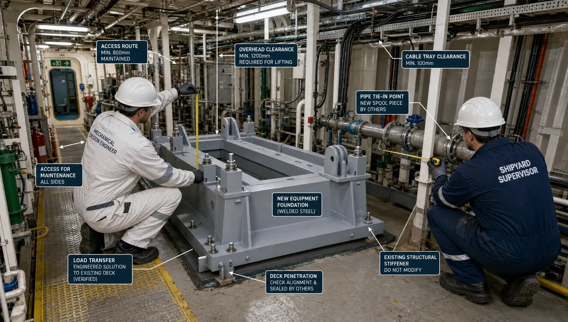
Check vessel, crane and deck constraints together
A crane capacity chart is not a complete lift approval. The crane may have enough rated capacity at the planned radius, while the vessel, quay, deck or receiving structure still limits the operation. For floating lifts, crane capacity interacts with vessel stability, ballast condition, trim, heel, boom angle, slew position and environmental limits.
Deck capacity is another frequent constraint. Heavy lifted items are often staged on grillages or skid systems before or after the lift. The local deck plating, stiffeners, frames, girders and underdeck supports must be checked for the real load footprint. Load spreading can reduce peak reactions, but only if the grillage has sufficient stiffness and bears where intended.
Existing vessels add further uncertainty. Drawings may be outdated, repairs may have changed local details, allowable loads may be unclear and access for reinforcement may be limited. In retrofit or decommissioning work, legacy data must be verified early so the lift design does not depend on assumptions that cannot be confirmed during mobilisation.
Verify lift points, temporary steel and local details
Lift points are small compared with the total module, but they are critical. Padeyes, trunnions, lifting lugs and temporary brackets must be checked for bearing, shear, tension, bending, weld capacity, local buckling and load introduction into the supporting structure. Out-of-plane effects and eccentricities should not be ignored.
Fabrication and inspection requirements are part of the design. A padeye detail that requires difficult overhead welding, tight access or complex fit-up may add schedule risk. Thick plates may introduce lamellar tearing concerns depending on material, weld detail and through-thickness demand. NDT access, weld sequencing and tolerance control should be considered before issuing drawings.
Temporary steel also needs a removal strategy. Offshore and shipyard teams often need to cut away padeyes, brackets or seafastening after the operation. If removal access is poor, hot work is restricted or coating repair is difficult, the project may lose time after the main lift is complete. A practical lift engineer considers the full temporary works lifecycle.
Design seafastening and grillages as part of the lift scope
The lift is rarely isolated from transport. Loads must often be moved from fabrication yard to quayside, loaded out, transported offshore, lifted, installed, then released. Seafastening and grillage design must therefore be integrated with the lifting arrangement, not designed afterwards.
Grillages provide support and load distribution, but they also define module elevation, rigging access, sea fastening locations, weld quantities and deck interface loads. If the grillage is too flexible, load sharing may be poor. If it is too stiff or overbuilt, it may increase steel weight, fabrication time and removal work. The best solution is usually the one that follows the real load path with the least unnecessary complexity.
Seafastening must resist transport loads, vessel accelerations, green water exposure where relevant and installation handling cases. It also needs to be practical to release within the offshore sequence. A perfect seafastening calculation is not enough if the offshore crew cannot access release points safely during the planned weather window.
Buildability is a safety issue
Buildability is often discussed as a cost topic, but in heavy lift engineering it is also a safety topic. Difficult fabrication details increase the risk of late changes, poor fit-up, non-conformances and incomplete inspection. Complicated welds or exotic materials can delay delivery and create avoidable uncertainty during mobilisation.
The principle is not unique to offshore work. In any site-led project, from marine fabrication to high-end building refurbishment, the value of smooth project management in renovation work comes from turning design intent into a sequence that trades can actually execute. Heavy lift engineering demands the same discipline, but with higher consequence: weld access, tolerances, inspection points and deck interfaces must be understood before mobilisation.
Good lift engineering therefore avoids unnecessary steel while protecting fabrication simplicity. Standard plate sizes, clear weld details, accessible bolted connections, realistic tolerances and logical assembly sequences can reduce both schedule risk and approval friction. For marine fabrication specifically, practical detailing is closely linked to engineering intent, as explained in Fusie Engineers’ article on why steel detailing matters in marine fabrication.
Documentation must be approval-ready, not just technically correct
Heavy lift engineering lives or dies by documentation. MWS, class societies and client reviewers need to see a clear chain from design basis to calculation to drawing to procedure. Missing assumptions, inconsistent weights or untraceable revisions can slow approval even when the engineering itself is sound.
Approval-ready documentation should show the logic of the design. The reviewer should understand which load cases govern, how the CoG tolerance was handled, how rigging loads were derived, which structural members were checked, what utilisation criteria were applied and how fabrication requirements connect to the drawings.
Typical heavy lift documentation may include:
- Design basis and governing criteria.
- Lift arrangement drawings, rigging plans and equipment data.
- Structural calculations for the lifted item, lift points, spreader systems, grillages, seafastening and deck interfaces.
- FEM reports with assumptions, boundary conditions, load cases, results and engineering interpretation.
- Vessel checks, stability information, mooring or motion analysis where required.
- Method statements, lift procedures, risk assessments, checklists and hold points.
- Fabrication drawings, weld details, material specifications, NDT requirements and inspection records.
Consistency between these documents is critical. If the rigging drawing shows a different sling angle from the calculation, or the procedure uses a different gross weight from the design basis, reviewers will rightly stop the process. Revision control is not administration; it is a safety control.
Turn calculations into a controlled operation
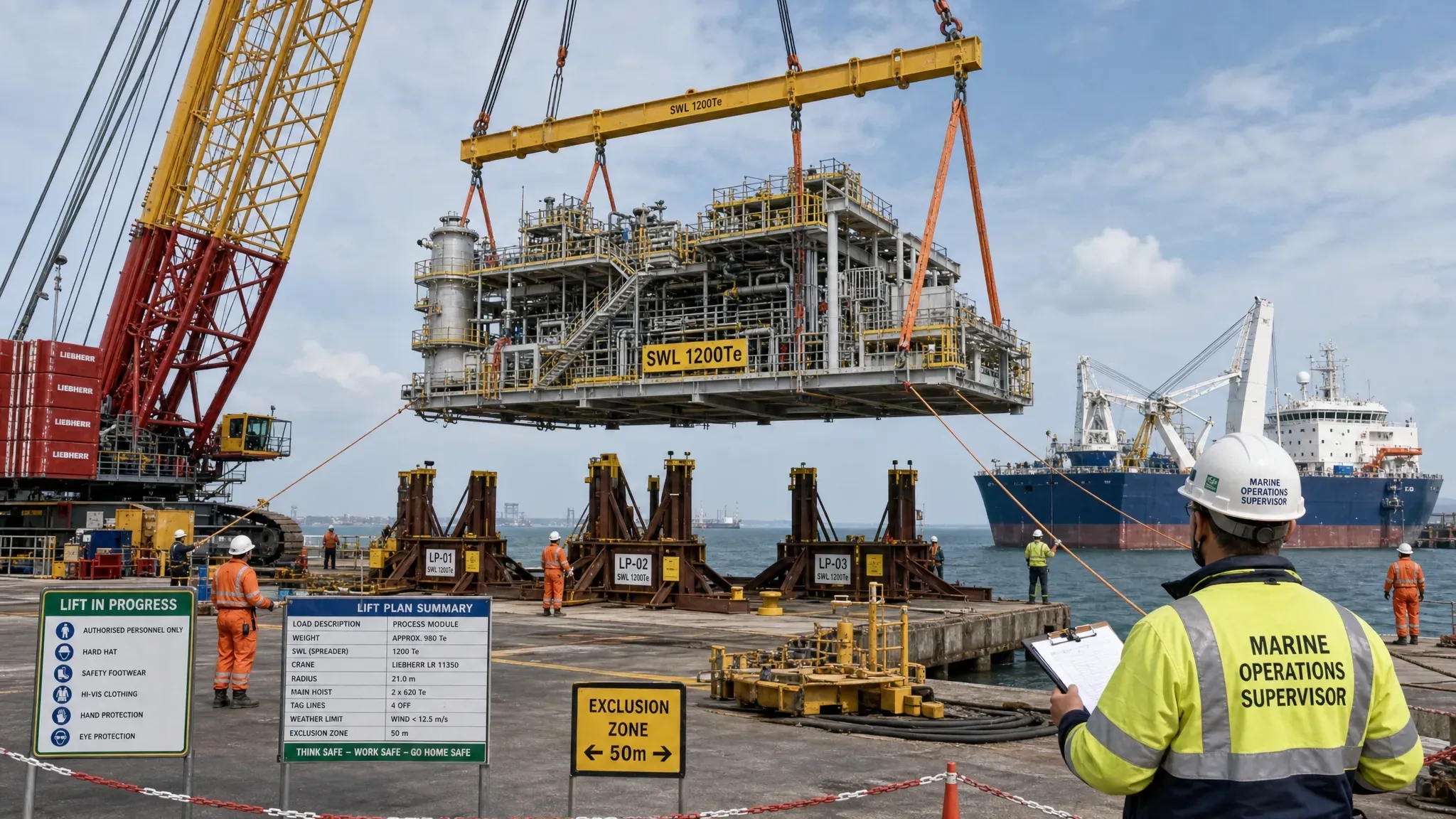
Calculations prove capacity, but procedures control execution. A lift engineer should ensure the technical work is translated into a sequence that operators, deck crew, crane teams, supervisors and reviewers can follow under real project conditions.
The procedure should cover rigging installation, pre-lift checks, load transfer, trial lift, slew path, clearances, set-down, contingency actions, communication protocol and abort criteria. For marine operations, it should also address ballasting, mooring or DP status, weather monitoring, vessel motions, tidal restrictions and safe access.
Hold points are especially useful. They create controlled moments to verify that the real operation still matches the engineered assumptions. Examples include confirmation of final weight, rigging certificate review, pre-tension checks, weather approval, trial lift inspection, ballast condition confirmation and release approval after set-down.
A heavy lift plan should also be understandable to non-engineering stakeholders. Project directors, HSE teams, client representatives and offshore supervisors do not need every calculation detail, but they do need clear visibility of critical assumptions, exclusion zones, operational limits and decision points. Technical animations and visualisations can support this when a complex lift sequence is difficult to explain with drawings alone.
Common mistakes every lift engineer should avoid
Even experienced project teams can lose time or create risk through avoidable mistakes. The most common issues are rarely caused by one major error. They usually come from small assumptions that were not aligned early enough.
Watch for these failure points:
- Treating preliminary weight and CoG data as final without contingency or verification.
- Selecting a dynamic amplification factor without considering the actual operation.
- Checking padeyes but not the surrounding structure or global load path.
- Ignoring sling tolerance, side loading, shackle articulation or rigging clashes.
- Optimising steel weight while creating fabrication details that are slow or risky to build.
- Separating lift calculations from seafastening, grillage, deck and stability checks.
- Sending incomplete or inconsistent documents to MWS or class reviewers.
- Leaving operational input until after the lift arrangement has already been fixed.
The best way to avoid these issues is to involve heavy lift engineering early, especially when vessel selection, fabrication planning, rigging procurement or approval schedules are still flexible. Early engineering does not remove complexity, but it gives the project more options to manage it.
What to share with a heavy lift engineering partner
When external support is needed, clear input data helps the engineering team move quickly without losing control. The ideal information package does not need to be perfect, but it should identify what is known, what is assumed and what still needs verification.
Useful inputs include general arrangement drawings, structural drawings, 3D models, weight reports, CoG data, lifting point concepts, crane curves, rigging inventory, vessel data, deck strength information, transport route, metocean criteria, class or MWS requirements, fabrication capabilities and project schedule constraints.
It is also useful to share the operational philosophy. Is the priority minimum steel, fastest fabrication, reduced offshore duration, reuse of equipment, limited hot work, simple approval, or vessel compatibility? The answer affects the design direction. A lift engineer cannot optimise the solution properly without understanding the project drivers.
How Fusie Engineers approaches heavy lift engineering
Fusie Engineers supports heavy lift engineering for offshore, maritime, energy, renewable, decommissioning and heavy civil scopes. The team combines structural engineering, mechanical design, marine engineering and naval architecture input so that lifting arrangements are not treated as isolated calculations.
Typical support can include concept development, lift point design, FEM calculations, spreader and lifting tool design, grillage and seafastening engineering, vessel and deck interface checks, stability and marine operation support, fabrication drawings and approval documentation. This integrated approach helps clients reduce rework, control steel use and keep designs practical for fabrication, installation and review.
The value is especially clear where a project has limited schedule margin or unusual interfaces. In a decommissioning lift, for example, existing structures may have uncertain condition, limited reinforcement access and strict transport constraints. Fusie Engineers has previously supported structural lift analysis and FEM verification for a decommissioning accommodation lift, showing how targeted engineering can support safe execution with minimal reinforcement.
For broader project planning, practical design choices also influence cost and approval risk. Fusie Engineers’ perspective on how design engineering can cut steel, cost and approval risk is directly relevant to heavy lift scopes where every tonne of temporary steel affects fabrication, transport and mobilisation.
Frequently asked questions
What does a lift engineer do in a heavy lift project? A lift engineer develops and verifies the technical basis for a lifting operation. This can include weight and CoG review, rigging load calculations, lift point design, structural checks, FEM analysis, crane and vessel interface checks, documentation and support for MWS or class approval.
Why is heavy lift engineering more than crane capacity checking? Crane capacity is only one constraint. The complete system also includes rigging geometry, dynamic effects, lifted structure strength, lift points, vessel stability, deck capacity, seafastening, weather limits, fabrication quality and operational procedure.
When should heavy lift engineering start? Heavy lift engineering should start during concept or early planning, before rigging, vessel selection, fabrication details and approval routes are fixed. Early involvement gives the project more options to reduce steel, simplify fabrication and avoid late redesign.
What information is most important for a lift engineer? The most important inputs are reliable weight and CoG data, drawings or models of the lifted item, proposed lift points, crane and rigging data, vessel or deck information, environmental criteria, applicable standards and the intended operational sequence.
How does FEM help in heavy lift engineering? FEM helps verify complex load paths, local stress concentrations, lift point reinforcement, grillages, deck interfaces and temporary structures. It is most effective when model assumptions, boundary conditions and load cases reflect the real lifting operation.
What causes delays in MWS or class approval? Common causes include incomplete design basis documents, inconsistent weights between drawings and calculations, unclear load cases, missing fabrication details, weak revision control and procedures that do not clearly connect to the engineering assumptions.
Need heavy lift engineering support?
If your project involves complex lifting, transport, seafastening, grillages, vessel interfaces or approval requirements, Fusie Engineers can support the work from concept through detailed engineering and operational readiness.
Work with a team that understands offshore and maritime constraints, fabrication realities, class and MWS expectations, and the cost of late engineering changes. Contact Fusie Engineers to discuss heavy lift engineering support for your next offshore, maritime or energy project.