Best software for structural engineers in complex projects
2026-05-19
For complex offshore, maritime and energy projects, the question is rarely which single programme is best. Structural engineers need a controlled software ecosystem that can carry a design from load definition and analysis through detailing, fabrication, approval and offshore execution.
That distinction matters. A seafastening frame, ship retrofit, heavy lift grillage or offshore installation structure may be affected by vessel motions, crane dynamics, fatigue, buckling, weld access, class rules, fabrication tolerances and mobilisation deadlines. The best software for structural engineers is the software stack that helps the team manage those interfaces safely, not simply the package with the most impressive solver.
A practical shortlist often looks like this:
- Global structural analysis and code checks: SACS, Sesam, STAAD.Pro, SCIA Engineer, RFEM, SAP2000 or Autodesk Robot, depending on sector and code basis.
- Advanced local FEA: ANSYS Mechanical, Abaqus, Femap with Nastran or similar tools for nonlinear, shell, solid, contact, buckling and fatigue-sensitive details.
- Marine operations and hydrodynamics: OrcaFlex, MOSES, AQWA, Sesam modules and project-specific motion or mooring tools.
- Ship design and stability: NAPA, Maxsurf, GHS and naval architecture platforms suited to hull form, hydrostatics, lightweight and intact or damage stability work.
- 3D modelling, BIM and fabrication detailing: Tekla Structures, Advance Steel, Revit, Inventor, SolidWorks, Navisworks and discipline-specific piping tools.
- Calculation automation and QA: Mathcad, Python, MATLAB and governed spreadsheets with clear version control and validation.
The best choice depends on project type, approval route, internal competence and the required deliverables. A tool that is excellent for building frames may not be suitable for offshore fatigue assessment. A detailed 3D model may be fabrication-ready but unsuitable for global analysis without idealisation. A powerful FEA package may still fail a review if the design basis, load cases and assumptions are not traceable.
What ‘best’ means in complex structural projects
In simple projects, software selection can be driven by familiarity, licence availability or local code checks. In complex projects, software selection becomes a risk decision.
For offshore and maritime scopes, the software must support the way the project will actually be engineered, reviewed, fabricated and installed. That means it should help engineers answer practical questions such as:
- Can the model represent the real load path without unnecessary complexity?
- Can load cases be traced from vessel motions, lifting arrangements, transport accelerations or operational limits?
- Can the output be reviewed by a marine warranty surveyor, class society or client’s technical authority?
- Can the results be translated into buildable drawings, weld details and fabrication packages?
- Can model revisions be controlled without losing the design history?
- Can the engineering team explain the assumptions clearly to operations, fabrication and project management?
This is why the strongest teams do not treat software as a replacement for engineering judgement. They use software to formalise decisions, test alternatives, document assumptions and reduce uncertainty before steel is cut or equipment is mobilised.
The principle is not unique to structural engineering. In manufacturing environments, an end-to-end development and production model helps reduce ambiguity between technical development, sourcing, sampling and scale-up. Offshore engineering operates in a very different risk environment, but the lesson is similar: tools only create value when the handovers between concept, analysis, detailing, production and execution are controlled.
Global structural analysis software
Global analysis tools are usually the backbone of the structural workflow. They are used to assess the overall behaviour of frames, decks, grillages, topsides, towers, modules, temporary works and offshore structures under defined load combinations.
For offshore structures, Bentley SACS is widely used for fixed offshore platforms, jackets, topsides, fatigue, transportation, lifting and code checking workflows. DNV Sesam is also established in offshore structural engineering, particularly where hydrodynamic loading, offshore standards and integrated workflows are important.
For building, industrial, bridge and general steel structures, tools such as STAAD.Pro, SCIA Engineer, RFEM, RSTAB, SAP2000 and Autodesk Robot Structural Analysis can be effective, provided the code basis, load combinations and modelling assumptions are appropriate. In marine and heavy lift projects, these tools may be useful for secondary structures, temporary works, equipment frames or support structures, but they must be used with a clear understanding of offshore-specific loading.
The key is not simply whether a programme can produce utilisation ratios. The key is whether the model is suitable for the design question. A global beam model may be correct for overall member checks, but inadequate for a padeye lug, deck penetration, bracket toe, complex weld group or local shell buckling issue. Conversely, a detailed local shell model may be inefficient and misleading if used before the global load path is understood.
Advanced FEA for local details and nonlinear behaviour
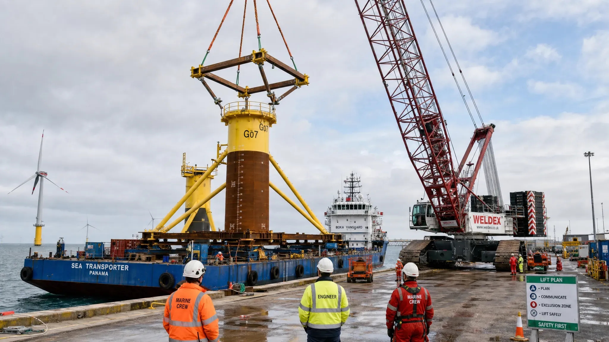
Advanced finite element analysis is essential when the design cannot be verified confidently using beam elements and standard hand calculations alone. In complex projects, local FEA is often used for padeyes, trunnions, grillage details, sea fastening brackets, underdeck reinforcement, vessel interface structures, skid bases, lifting beams, custom tools and fatigue-sensitive weld regions.
Packages such as ANSYS Mechanical, Abaqus and Femap with Nastran are commonly used where engineers need refined shell or solid modelling, nonlinear contact, plasticity checks, bolt preload, local buckling, fatigue assessment or complex boundary conditions.
However, detailed FEA can create a false sense of certainty if the inputs are weak. Mesh density, element type, load application, restraints, contact definitions and material assumptions can change the outcome significantly. In offshore and heavy lift work, the real challenge is often not building a detailed model. It is defining realistic boundary conditions that represent the vessel, lifting configuration, transport support, sea state, installation method or temporary restraint.
For that reason, local FEA should be linked back to global analysis and operational procedures. If a grillage is checked under transport accelerations, the source of those accelerations must be documented. If a lift point is checked under sling loads, the sling arrangement, dynamic amplification factor, skew load factor and centre of gravity assumptions must be clear. If a vessel deck is locally reinforced, the underdeck structure and allowable capacities must be understood.
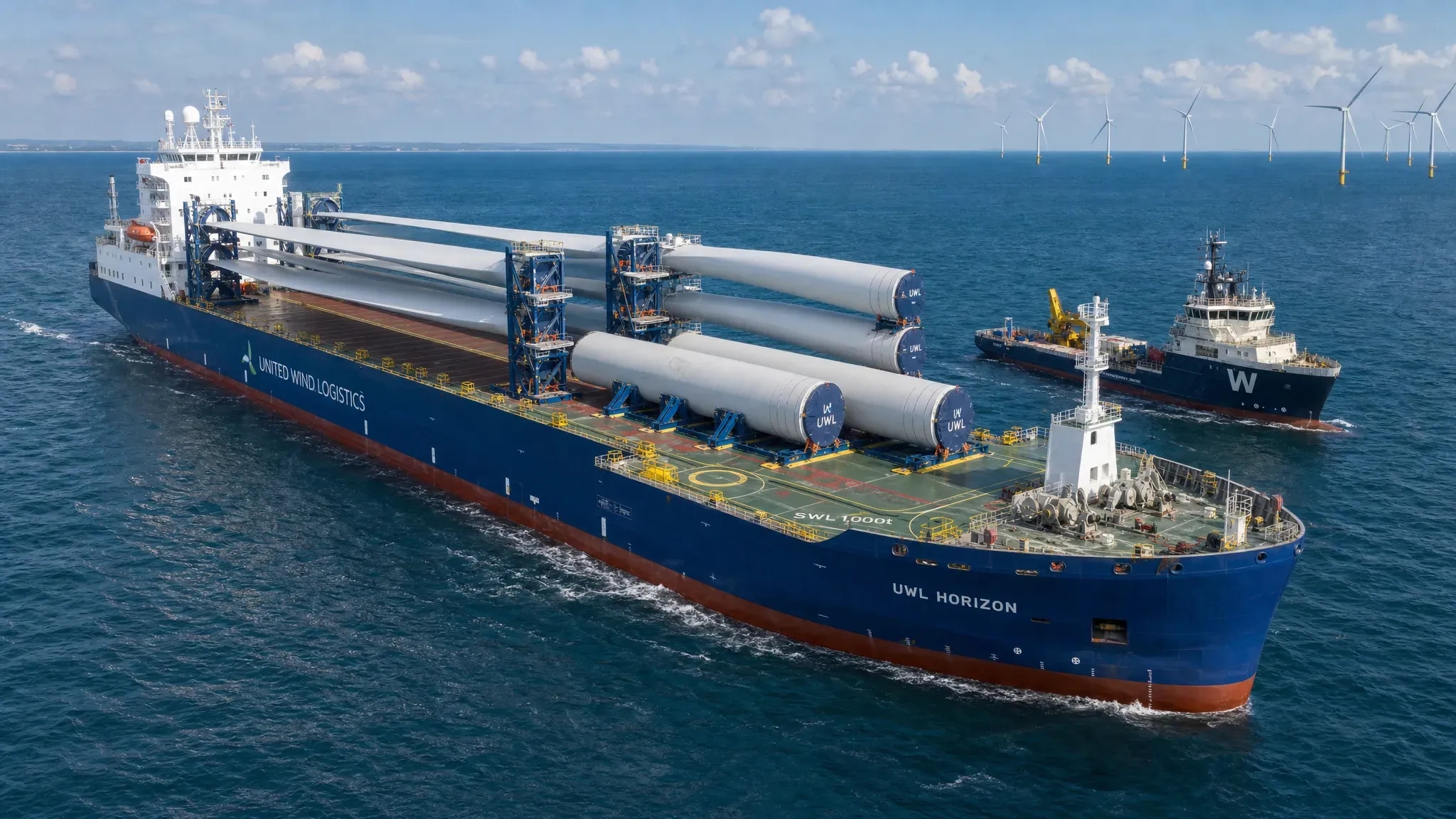
Marine operations and hydrodynamic software
Marine operations bring structural engineering into a dynamic environment. A structure that is safe in a static workshop condition may behave very differently during tow, offshore lifting, upending, floatover, launch, mooring or installation.
Tools such as OrcaFlex are widely used for dynamic analysis of marine systems, including mooring lines, cables, risers and installation operations. MOSES and AQWA are also used in offshore transportation and hydrodynamic workflows, particularly where vessel motions, hydrostatics, wave loading and marine operations need to be assessed.
For structural engineers, the value of marine operations software is not only the simulation itself. It is the ability to derive credible loads and operational limits for structural verification. For example, a seafastening design may depend on transport accelerations. A lifting frame may depend on crane vessel motions and dynamic amplification. A mooring structure may depend on line tensions under environmental conditions. A temporary installation tool may depend on clearances, motion envelopes and impact cases.
This is where coordination between naval architects, marine engineers and structural engineers becomes critical. The structural model must not be isolated from the marine operation. If the motion analysis changes, the structural loads may change. If the structural design becomes heavier, stability and vessel capacity may change. If the installation method changes, the load path and approval documentation may need to be revised.
Ship design, stability and retrofit software
Ship design and vessel retrofit projects require a different software mindset. The structure is not only a steel object, it is part of a floating system with stability, hull strength, class requirements, piping, equipment, access, maintainability and operational constraints.
Software such as NAPA and Maxsurf can support naval architecture workflows, including hull form, hydrostatics, stability and related design evaluations. GHS is also commonly used for stability work in marine projects. In retrofit and conversion projects, these tools may need to interface with 3D scan data, legacy drawings, class-approved documentation and practical onboard surveys.
Vessel retrofit engineering is often constrained by incomplete information. Legacy drawings may not match the current vessel condition. Existing penetrations, piping routes, underdeck stiffeners, access restrictions and class notations can limit the design space. Structural software is useful, but the real value comes from combining analysis with practical survey interpretation, interface management and approval discipline.
For example, adding a skid, carbon capture unit, crane foundation, piping system or new access platform may affect local strength, global weight, stability, fatigue, fire zones, maintenance access and class approval. A good software workflow helps identify these interfaces early, before fabrication or mobilisation decisions are locked in.
BIM, 3D modelling and steel detailing software
Analysis software verifies whether a structure can work. Detailing software helps ensure it can be built.
For complex steel projects, Tekla Structures is a leading platform for fabrication-ready modelling, shop drawings, assemblies, connection details and material take-offs. Advance Steel, Revit, Inventor, SolidWorks and other 3D modelling platforms also play important roles depending on the project type, client standards and fabrication workflow.
In marine fabrication, good detailing must account for more than geometry. It must consider weld access, plate thickness transitions, fit-up sequence, coating access, transport limitations, lifting points, temporary supports and inspection requirements. A model that looks clean on screen may still be expensive to fabricate if it introduces unnecessary welds, tight tolerances, inaccessible details or avoidable material complexity.
This is why analysis and detailing should not be separated too late. If a structural engineer optimises a frame without considering fabrication, the final design may save steel but increase workshop hours. If a detailer models a connection without understanding fatigue, load paths or class requirements, the result may create review problems. In complex projects, the best software workflow connects analysis intent with fabrication reality.
Calculation automation, spreadsheets and engineering QA
Even in highly digital projects, many critical decisions still pass through calculation sheets. Mathcad, Python, MATLAB and controlled spreadsheets are widely used for load derivation, code checks, fatigue post-processing, bolt checks, weld checks, plate buckling, padeye calculations, lifting checks and reporting.
The benefit of calculation automation is speed and consistency. The risk is uncontrolled reuse. A spreadsheet that worked for one project can become dangerous if assumptions, units, safety factors or code clauses are copied without review.
For complex structural engineering, calculation tools should be treated as part of the quality system. They need clear inputs, revision control, validation checks, reviewer notes and traceable outputs. Python and MATLAB can be powerful for repetitive analysis and post-processing, but scripts also need governance. A script that generates hundreds of load combinations must be easier to audit, not harder.
Good software for structural engineers does not only calculate. It supports a defensible engineering record.
How to choose the right software stack
The best software stack should be selected from the project requirements backwards. Start with the design basis, approval path, project interfaces and deliverables, then decide which tools are required.
For offshore and maritime projects, the following selection criteria are especially important:
- Approval readiness: The software output should support review by MWS, DNV, Lloyd’s Register, ABS or the relevant authority, but the report must still explain assumptions and methodology clearly.
- Load traceability: Loads should be linked to the real source, such as vessel motions, crane data, environmental criteria, transport conditions, operating limits or class rules.
- Interoperability: Geometry, loads and results should be transferred between analysis, detailing and reporting tools without uncontrolled manual rework.
- Constructability: The workflow should help identify difficult welds, heavy plates, inaccessible details and fabrication constraints early.
- Scalability: The software should handle the required model size and complexity without becoming too slow for design iterations.
- Competence and QA: The engineering team must understand the tool deeply enough to challenge the output and document limitations.
- Documentation quality: The final deliverables must be clear enough for client review, class approval, fabrication and offshore execution.
Class and industry rules remain essential. Software can help apply requirements, but it does not replace the need to understand the relevant standards, load factors and acceptance criteria. For maritime projects, reviewing the applicable DNV rules and standards or other class requirements early helps prevent rework later in the design process.
Common software mistakes in complex projects
One of the most common mistakes is using a detailed 3D model as if it were automatically suitable for analysis. Fabrication models contain real plates, stiffeners, holes and connections, but analysis models often need idealisation. If this conversion is not controlled, engineers may introduce stiffness errors, duplicate elements, unrealistic restraints or incorrect load paths.
Another mistake is over-refining local FEA before the governing load cases are stable. A very detailed padeye model is of limited value if the centre of gravity, sling angle, dynamic factor or operational limit is still uncertain. The design should mature in the right sequence: define the operation, derive the loads, verify the global load path, then refine the local details.
A third mistake is separating software users by discipline without interface ownership. The marine team may calculate motions, the structural team may design the frame, the detailers may build the fabrication model and the project team may prepare the method statement. If nobody owns the interfaces between these outputs, errors can appear late, when they are expensive to correct.
Finally, teams sometimes judge software by visual quality rather than technical reliability. A clean model, attractive render or automated report can still hide weak assumptions. In approval-driven work, reviewers care about design basis, load combinations, boundary conditions, utilisation, weld details, revision control and operational limitations.
What Fusie Engineers looks for in software-led delivery
At Fusie Engineers, software is used as part of practical engineering delivery, not as isolated modelling. For offshore structural design, heavy lift engineering, ship design, vessel retrofits, piping, marine engineering, steel detailing and renewable energy projects, the objective is always the same: safe, buildable and approval-ready design.
That means software choices are guided by the project outcome. A seafastening grillage may need global checks, local FEM, vessel interface verification, steel detailing and documentation for MWS review. A vessel retrofit may require structural calculations, piping interfaces, stability considerations, class documentation and fabrication coordination. A heavy lift project may require lifting arrangements, padeye checks, structural reinforcement, transport checks and clear operational limits.
The right workflow can reduce steel use, fabrication time and rework, but only when the design team understands the constraints around the model. Vessel capacities, underdeck structures, weld access, lifting geometry, class rules and offshore weather windows all influence engineering decisions.
For technical directors, engineering managers and project directors, the question is not whether a partner has software licences. The more important question is whether the partner can use those tools to make practical engineering decisions, produce clear documentation and support the project through review, fabrication and execution.
Frequently asked questions
What is the best software for structural engineers? There is no single best software for every complex project. SACS, Sesam, STAAD.Pro, SCIA, RFEM, SAP2000, ANSYS, Abaqus, Tekla and marine tools all have strong use cases. The best choice depends on the structure, load cases, code basis, approval route and deliverables.
Is FEA software enough for offshore structural design? No. FEA is only one part of the workflow. Offshore structural design also requires a sound design basis, marine load definition, operational understanding, code knowledge, fabrication input, documentation and approval support.
What software is commonly used for seafastening and grillage design? Engineers may use global structural analysis tools such as SACS, STAAD.Pro, Sesam or similar packages, combined with local FEA tools such as ANSYS, Abaqus or Femap with Nastran. Detailing may then be completed in Tekla Structures or another fabrication modelling platform.
How important is class or MWS acceptance when choosing software? It is very important, but software acceptance alone is not enough. Reviewers need traceable assumptions, clear load cases, appropriate safety factors, model descriptions, calculation reports and drawings that match the design intent.
Should structural engineers learn Python or automation tools? Yes, especially for repetitive calculations, load combination generation, post-processing and reporting. However, automation must be validated and controlled. A fast script is only useful if the engineering logic is correct and reviewable.
Can external engineering support help if our internal team already has software? Yes. Many project teams have licences and skilled engineers but need additional capacity, specialist offshore experience, local FEM support, heavy lift knowledge, detailing coordination or approval-ready documentation during demanding project phases.
Need support choosing or using the right structural engineering workflow?
Complex projects need more than software access. They need engineering judgement, controlled interfaces and practical design decisions that hold up during fabrication, approval and offshore execution.
Fusie Engineers supports offshore, maritime, renewable energy, decommissioning, heavy lift, ship design, retrofit, piping and steel detailing projects with a project-driven engineering approach. If your team needs structural design support, local FEM, seafastening and grillage engineering, marine operation input, class documentation or fabrication-ready detailing, contact Fusie Engineers to discuss the scope and the right workflow for your project.