Dogger Bank wind farm lessons for transport and installation
2026-05-31
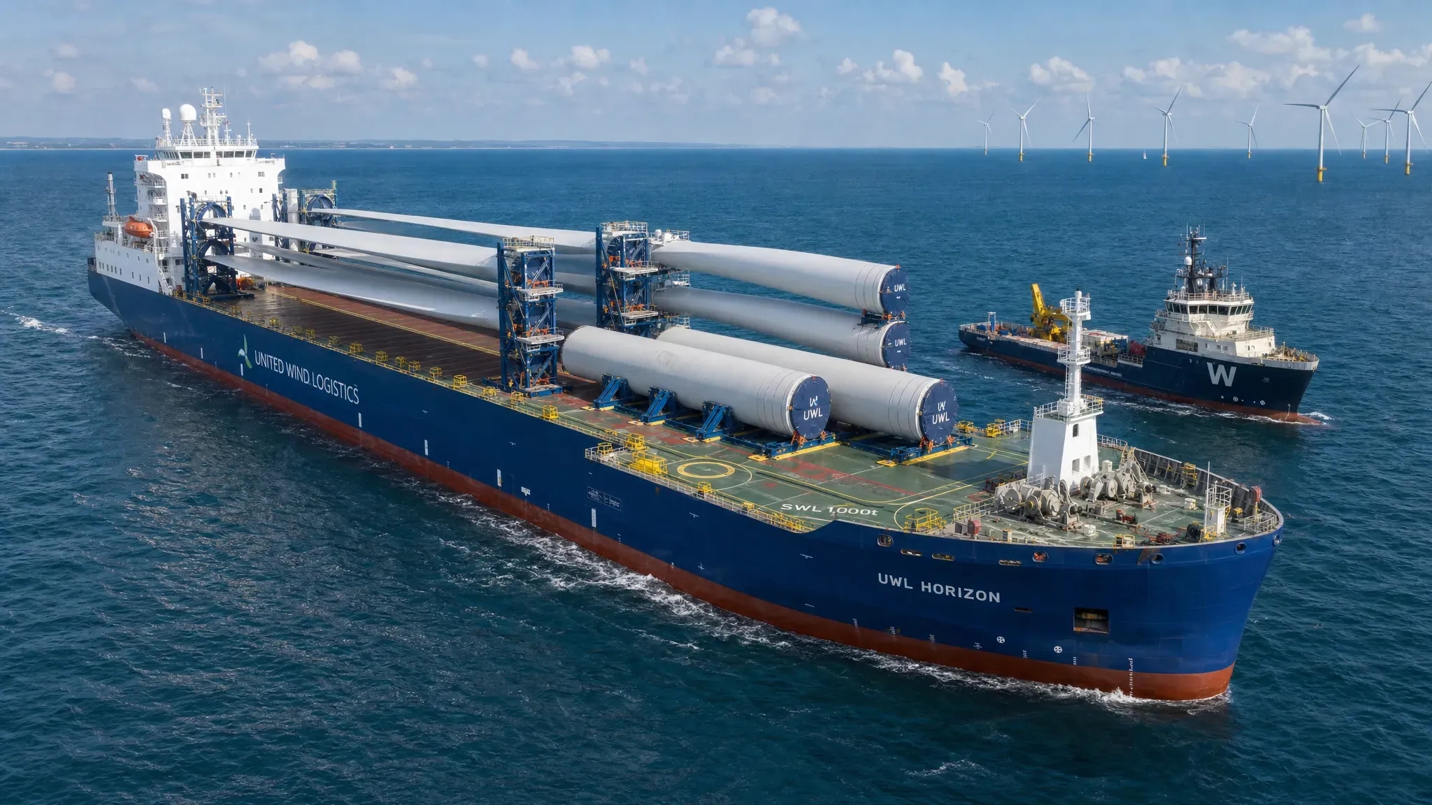
When the Dogger Bank wind farm is discussed, attention often goes to its generating capacity. For engineering managers, marine contractors and offshore installation teams, the more useful lesson is how a project of this scale forces transport and installation decisions to become more industrialised, more traceable and more tightly connected to design.
Dogger Bank Wind Farm describes the project as a 3.6 GW development delivered in three 1.2 GW phases, located more than 130 km off the north-east coast of England. That distance, combined with very large turbine components, repeated foundation and cable scopes, and high vessel utilisation, makes it a strong reference point for future offshore wind projects.
The Dogger Bank wind farm is not a template that can be copied directly. Every vessel, port, component supplier, seabed condition and approval route is different. But it does show where transport and installation engineering must be strong if offshore wind, maritime, decommissioning and heavy marine projects are to remain safe, buildable and commercially controlled.
Why Dogger Bank matters beyond project size
Large offshore wind projects change the relationship between engineering and operations. A single temporary support detail, lift point assumption or seafastening weld can be repeated across many transports. If that detail is inefficient, difficult to fabricate or unclear to approve, the cost is multiplied. If it is robust, simple and well documented, the benefit is also multiplied.
Dogger Bank also reflects a wider market shift. Turbine components are larger, offshore sites are further from shore, installation vessels are more specialised and weather windows are increasingly valuable. Transport and installation can no longer be treated as a late-stage method statement exercise. It has to influence early structural design, vessel selection, port planning, fabrication sequencing and approval strategy.
For project directors and lead engineers, the lesson is clear: the most valuable engineering is not only the calculation that proves a structure is strong. It is the judgement that makes the design practical to fabricate, install, inspect, approve and repeat offshore.
Lesson 1: transport and installation engineering must start early
A component can be suitable for its final offshore function and still be difficult to transport or install. Temporary load cases often expose issues that are not visible in the in-place design. Local plate thickness, stiffener layout, access for welding, allowable deck loads, centre of gravity uncertainty and sling geometry can all become critical before the component ever reaches its operational location.
On large wind projects, early decisions affect several downstream packages. A foundation design influences grillage reactions. A nacelle or tower transport concept influences sea fastening, deck layout and lifting clearances. Port handling assumptions influence temporary support design and SPMT routing. Cable installation planning influences vessel sequencing and interface windows.
Typical early load cases that should be considered include:
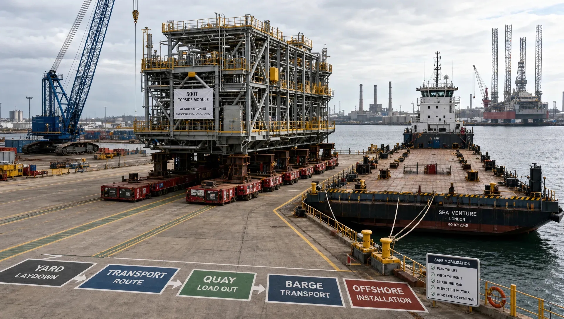
- Quayside lifting, tailing and turning operations
- SPMT transport and load-out reactions
- Vessel accelerations during sea transit
- Temporary support and grillage load distribution
- Lashing, stopper and seafastening forces
- Offshore upending, lifting and lowering operations
- Accidental or contingency cases required by MWS or class review
The earlier these conditions are discussed, the easier it becomes to avoid late reinforcement, rushed fabrication changes and approval delays. For projects influenced by the scale of the Dogger Bank wind farm, the transport philosophy should be part of the design conversation from the beginning, not added after procurement.
Lesson 2: seafastening is a structural design problem, not a detail
As turbine and foundation components grow, seafastening becomes more than deck steel. It is a temporary structural system that has to transfer dynamic loads safely into the vessel without creating local overstress, fatigue concerns or impractical fabrication work.
A good seafastening design balances stiffness, strength and buildability. If the grillage is too stiff, it may attract concentrated loads and overload the vessel deck or underdeck structure. If it is too flexible, it may allow excessive movement or create fatigue-sensitive details. If the weld layout is too complex, fabrication time increases and inspection becomes harder. If the release concept is not practical offshore, the installation sequence can slow down during the most expensive part of the operation.
Dogger Bank-level scale makes this especially important because small inefficiencies repeat. Extra steel per grillage, unnecessary full-penetration welds, poor access for NDT or unclear cutting points may look manageable on one transport, but they become major schedule and cost drivers across a campaign.
The best temporary works are not over-engineered. They are clear in load path, efficient in steel use, realistic for fabrication and easy for offshore crews to understand under operational pressure.
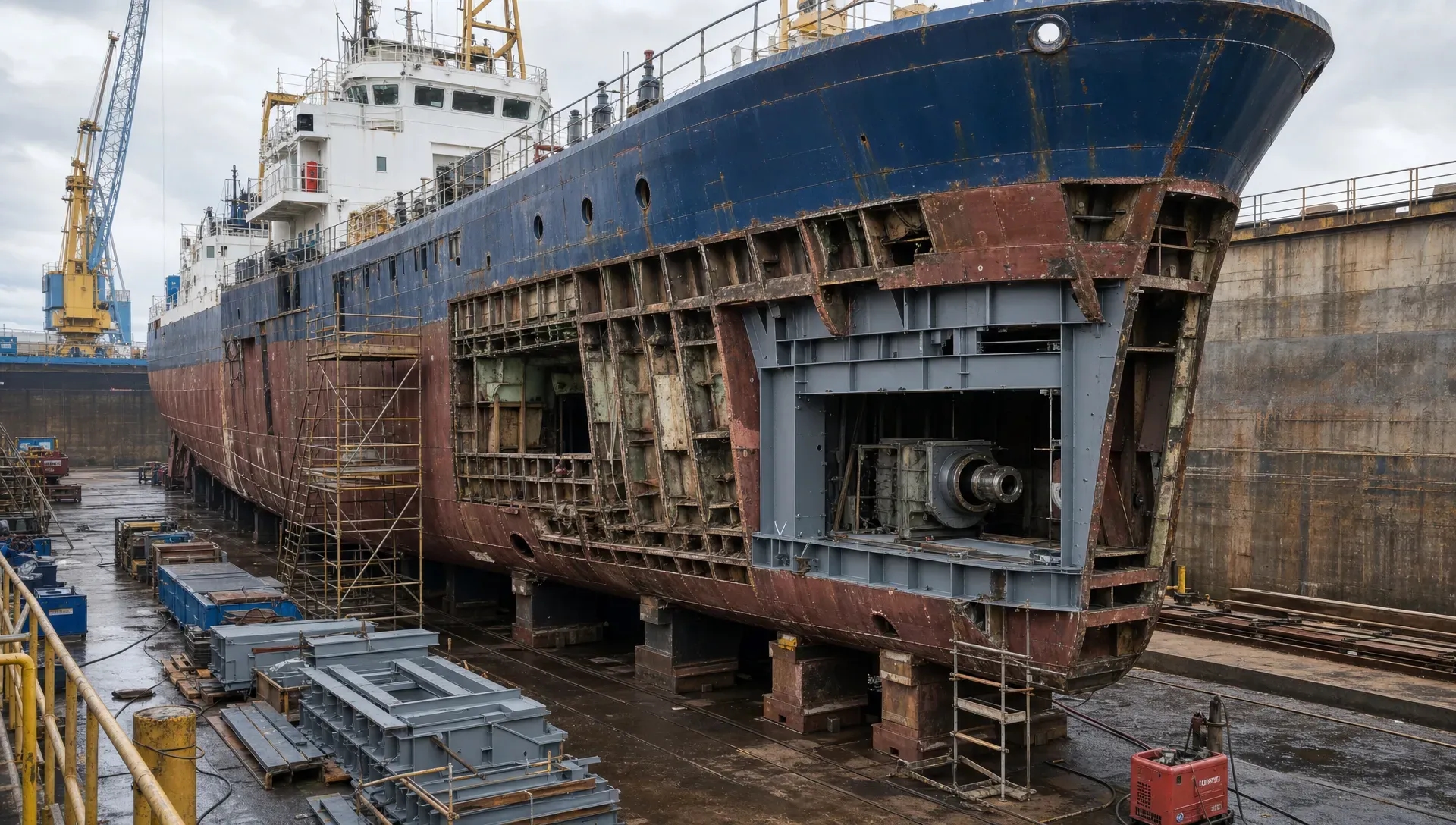
Lesson 3: the vessel is part of the engineering system
Transport and installation design must treat the vessel as an active part of the structure. Deck strength, underdeck framing, stability, crane radius, grillage interface, sea state limitations, mooring arrangement and ballast operations all influence what can be safely installed.
This is a frequent challenge for marine contractors and vessel owners. A vessel may have adequate deck area but insufficient local deck capacity. It may have crane capacity but limited outreach for a specific lift geometry. It may be suitable for transit but require local reinforcement for concentrated grillage reactions. It may need temporary modifications, piping relocation or access changes before mobilisation.
For vessel retrofits and offshore wind mobilisation scopes, engineering should connect naval architecture, structural design and marine operations. Stability checks, motion analysis, structural verification and fabrication drawings should not be separate conversations. They need to describe the same operation from different technical angles.
This is where practical design discipline matters. It is not enough to create a calculation model that passes. The design must respect how the shipyard will fabricate the steel, how the vessel crew will operate around it, how the MWS reviewer will assess it and how the offshore team will remove or reuse it.
Lesson 4: repeatability is a safety and cost control
Large offshore wind projects depend on repetition. Repetition can reduce risk when the engineering is standardised, documented and improved through feedback. It can also repeat mistakes if early details are weak.
For Dogger Bank wind farm transport and installation lessons, repeatability is one of the most important themes. Standard grillage modules, consistent lifting markings, clear tolerances, predictable weld details and well-defined inspection points help reduce ambiguity. They also support faster fabrication and easier approval because reviewers and site teams can understand the pattern.
However, standardisation should not mean ignoring actual interfaces. A standard support may need adjustment for a specific vessel frame location. A repeated sea fastening detail may need local modification because of deck camber, access constraints or component tolerance. A repeated lift plan may still require updated weights, centres of gravity and rigging certificates.
The practical target is controlled repeatability. Keep the design logic consistent, but verify each interface with the real vessel, real component data and real installation sequence.
Lesson 5: distance offshore changes the risk profile
Dogger Bank is far enough offshore that logistics become a major engineering consideration. Longer transits reduce flexibility. Weather delays have greater knock-on effects. Crew transfer, bunkering, spare parts, port calls and vessel availability all become more critical. A missed window may affect not only one lift, but an entire installation sequence.
For transport and installation teams, distance offshore means operability must be realistic. Motion limits, allowable sea states, transit duration, fatigue exposure and contingency plans all need to be aligned with the vessel and component design. If the engineering assumes an ideal sequence but the marine operation requires repeated waiting, repositioning or partial completion, the design may not be robust enough for real execution.
Large offshore programmes also depend on people logistics. Specialist engineers, supervisors, client representatives and installation personnel often move between project regions for long assignments. When teams are mobilised internationally, non-technical planning can still affect readiness. For example, contractors relocating key personnel and families to an Australian project hub may need practical relocation support for families moving to Australia so housing and schooling do not become distractions during mobilisation. The broader lesson is that every interface, technical or human, should be planned before it becomes a schedule risk.
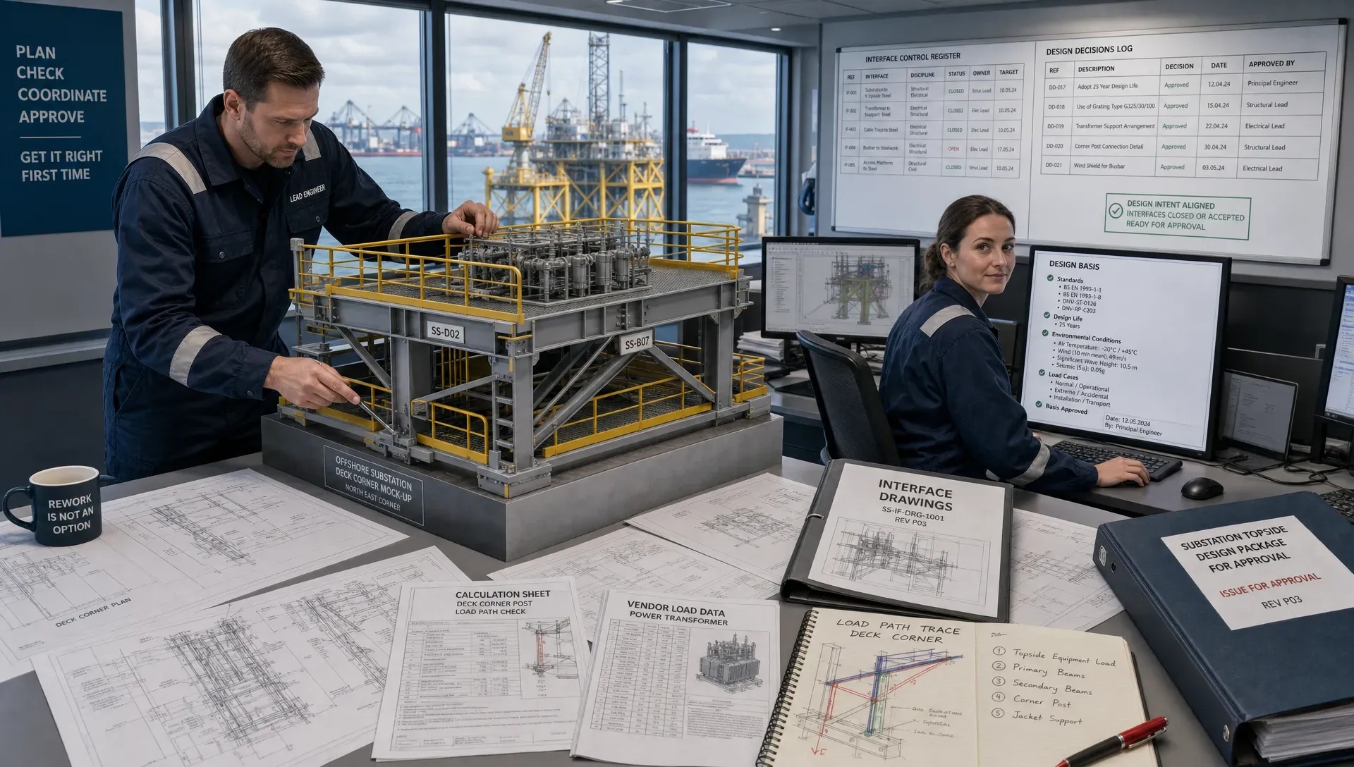
Lesson 6: approval readiness is a schedule requirement
For high-value offshore operations, approval is not a formality. MWS, class societies and client reviewers need to understand the design basis, assumptions, load cases and fabrication details. Incomplete documentation can delay mobilisation even when the engineering concept is sound.
Approval-ready transport and installation engineering should make the load path easy to follow. Reviewers should be able to trace the component weight, centre of gravity, environmental assumptions, vessel motions, grillage reactions, weld design and structural verification without searching through disconnected files.
A strong documentation package typically includes a clear design basis, calculation reports, FEM outputs where required, vessel information, load case definitions, rigging arrangements, seafastening drawings, fabrication details, inspection requirements and method statement interfaces. The exact scope depends on the operation and reviewer requirements, but the principle is consistent: assumptions must be visible, justified and aligned across documents.
This is especially important when project teams are working under tight mobilisation dates. Fast answers are useful only if they are technically defensible and reviewable. A calculation that cannot be checked, or a drawing that does not match the model, can create more risk than delay.
Lesson 7: installation interfaces matter as much as major lifts
Transport and installation discussions often focus on the biggest lifts, but many offshore delays come from interfaces. Cable pull-ins, secondary steel, boat landings, access platforms, temporary guides, survey references, bolting access, scour protection and deck handling all influence the overall operation.
The Dogger Bank wind farm includes major electrical infrastructure and long-distance offshore transmission requirements, as described by project partners including SSE Renewables. For engineering teams, this reinforces a wider point: offshore wind is not only turbines and foundations. It is a system of structures, vessels, cables, ports and operational procedures.
Interface engineering should ask practical questions. Can crews access the bolts safely? Can the temporary guide be removed without hot work in a poor weather window? Are tolerances realistic for offshore alignment? Does the cable route conflict with vessel positioning? Is there enough clearance for rigging, tag lines and crane motion? These issues may appear small compared with a major lift, but they can determine whether a method is efficient offshore.
Lesson 8: visualisation improves understanding before mobilisation
Complex offshore operations are difficult to explain through drawings alone. Technical animation and visualisation can help align clients, MWS reviewers, HSE teams, vessel crews and fabrication teams before the operation begins.
This is not about making a presentation look better. It is about reducing ambiguity. A well-prepared operation visualisation can show lift sequence, vessel positions, exclusion zones, rigging changes, component orientation, mooring arrangement and removal steps. It can also support tender submissions, QHSE briefings and offshore readiness reviews.
For large transport and installation campaigns, visual clarity can prevent misunderstandings between engineering intent and site execution. When the operation is expensive, weather-sensitive and safety-critical, that clarity has real value.
Applying the lessons to future offshore and maritime projects
Dogger Bank is an offshore wind project, but the lessons apply far beyond offshore wind. Heavy lift transport, vessel retrofits, decommissioning, dredging equipment, bridge installation systems, offshore substations, floating wind prototypes and traditional energy projects all face similar pressures. The components may differ, but the need for safe, practical and approval-ready engineering is the same.
Before committing to a transport or installation concept, project teams should challenge the engineering from several angles:
- Is the temporary load path clear from component to vessel structure?
- Are the governing load cases agreed early enough to influence design?
- Can the grillage and seafastening be fabricated quickly with realistic weld access?
- Are vessel limitations, underdeck structure and stability properly considered?
- Is the documentation suitable for MWS, class and client review?
- Can offshore crews understand and execute the method under real conditions?
- Does the design reduce steel, downtime and rework without reducing safety margin?
These questions help prevent a common offshore problem: a technically correct design that is difficult to build, slow to approve or awkward to execute.
How Fusie Engineers supports transport and installation challenges
Fusie Engineers supports offshore, maritime and energy projects where structural design, heavy lift engineering, vessel behaviour and buildability have to work together. For transport and installation scopes, that can include seafastening, grillages, custom tools, lifting arrangements, FEM verification, stability input, mooring-related engineering, vessel retrofit support, steel detailing and approval documentation.
The value is not only extra engineering capacity. It is coordinated judgement across structural engineering, naval architecture, marine operations and fabrication. Designs must be strong enough for offshore loads, practical enough for shipyards and fabrication teams, and clear enough for MWS or class society review.
For teams selecting support on complex offshore scopes, this article on how to choose engineering design services for offshore projects explains what to look for in an engineering partner. For fabrication-driven work, why steel detailing matters in marine fabrication gives further context on turning engineering intent into buildable, approval-ready steelwork.
The Dogger Bank wind farm shows where the offshore wind sector is heading: larger components, longer offshore distances, tighter vessel schedules and higher expectations for documentation. The engineering response must be practical, integrated and ready for execution.
Frequently asked questions
What is the main Dogger Bank wind farm lesson for transport and installation? The main lesson is that transport and installation engineering must be integrated early. Large offshore projects multiply the impact of every temporary support, lift arrangement, vessel interface and approval document, so late decisions can create major cost and schedule risk.
Why do larger wind turbine components make seafastening more complex? Larger components increase dynamic loads, centre of gravity sensitivity, deck reactions and fabrication demands. Seafastening must be designed as a structural system that safely transfers loads into the vessel while remaining practical to fabricate, inspect and remove.
How early should T&I engineers be involved in an offshore wind project? T&I engineers should be involved before key design and procurement decisions are frozen. Early input can influence component support points, vessel selection, grillage design, lift strategy, port handling and approval planning.
What documentation is usually needed for MWS or class approval? Requirements vary by project, but typical documentation includes the design basis, calculation reports, FEM verification where required, vessel data, load cases, rigging arrangements, seafastening drawings, fabrication details, inspection requirements and method statement interfaces.
Do Dogger Bank lessons apply outside offshore wind? Yes. The same principles apply to maritime retrofits, heavy lift projects, decommissioning, dredging equipment, shipbuilding, offshore substations and traditional energy projects where temporary loads, vessel interfaces and approval readiness are critical.
Need transport and installation engineering support?
If your project involves offshore structures, heavy lift operations, vessel modifications, seafastening, grillages or approval-critical documentation, Fusie Engineers can support the engineering from concept through detailed design and execution readiness.
Contact Fusie Engineers to discuss practical, buildable and review-ready solutions for your next offshore, maritime or energy project.