

How engr design improves fabrication and installation
2026-07-06
Fabrication and installation performance is won or lost long before steel reaches the workshop. In offshore, maritime and energy projects, the quality of engineering decisions made during design directly affects weld hours, fit-up quality, lifting safety, class approval, vessel mobilisation and offshore execution risk.
In many project schedules, engr design appears as a compressed line item. In practice, it should not be treated as a drawing package only. It is the process of turning structural, mechanical, marine and operational requirements into a design that can be fabricated, transported, lifted, installed, inspected and approved without avoidable rework.
A technically correct design can still fail the project if it is difficult to build, too heavy for the selected vessel, unclear for the fabricator, or incomplete for Marine Warranty Surveyor review. Good engr design closes that gap. It connects calculations with fabrication methods, vessel constraints, temporary works, installation sequencing and approval documentation.
What engr design should control before steel is cut
The first contribution of good engr design is control. Offshore and marine projects rarely fail because one isolated calculation was missing. Problems usually appear when assumptions are not aligned across disciplines, or when engineering is released before the fabrication and installation strategy is mature enough.
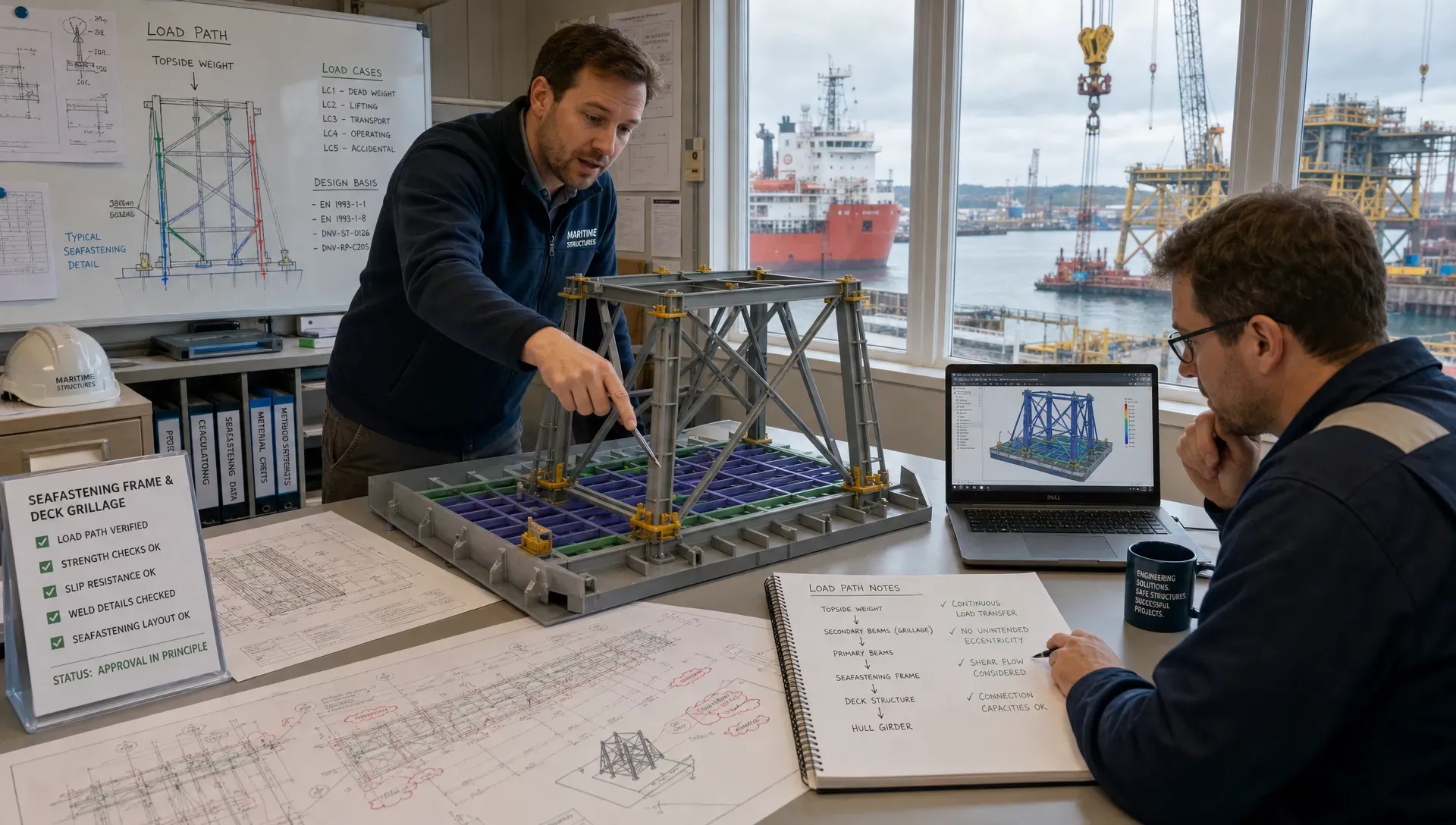
A controlled design basis should define the load cases, environmental criteria, vessel data, fabrication assumptions, class requirements and operating limits before detailed drawings are produced. For a grillage, seafastening frame, lifting tool, retrofit structure or vessel modification, this means the engineer is not only asking whether the member is strong enough. The more useful question is whether the complete system works under real project conditions.
Key inputs typically include:
- Operating, transit, lifting, temporary and survival load cases
- Vessel deck capacities, underdeck structure, stability limits and motion behaviour
- Interface data from equipment, foundations, piping, hull structures and installation aids
- Fabrication constraints such as plate availability, welding access, tolerances and coating sequence
- Approval requirements from MWS, DNV, Lloyd’s Register, ABS or other relevant bodies
When these inputs are fixed early, fabrication teams receive fewer late changes, procurement can order material with more confidence, and installation teams can plan around verified capacities rather than assumptions.
From correct geometry to buildable steel
Fabrication speed depends heavily on the level of buildability engineered into the design. A model can look clean on screen while still creating unnecessary work on the shop floor. Tight access for welding, awkward cope details, excessive plate thickness variation, hidden clashes, poor splice locations and unclear tolerances can all slow fabrication.
Practical engr design considers how steel will be cut, assembled, welded, inspected, blasted, painted and transported. The goal is not to make every structure simple, since offshore structures are often inherently complex. The goal is to remove complexity that adds no structural or operational value.
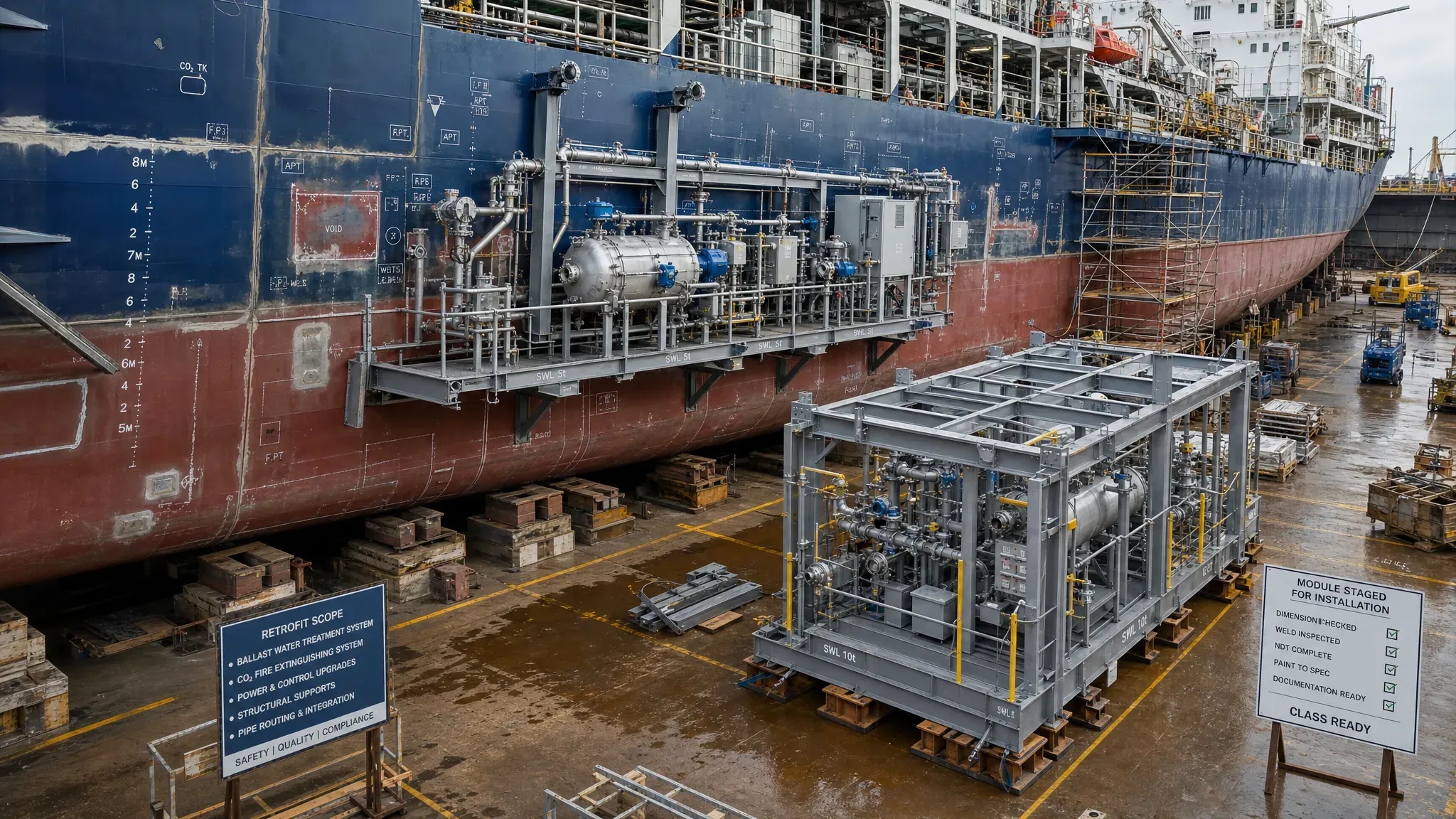
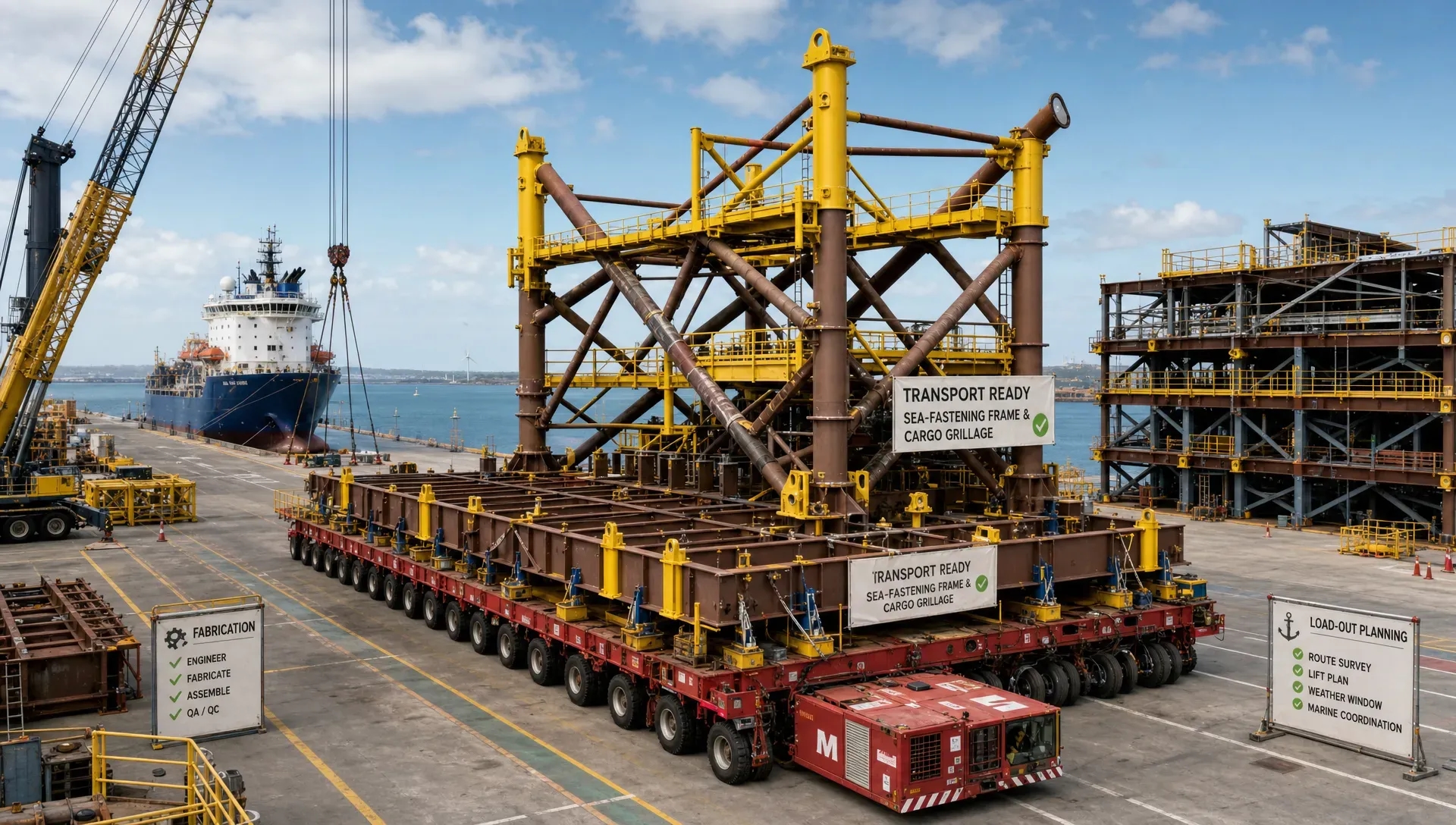
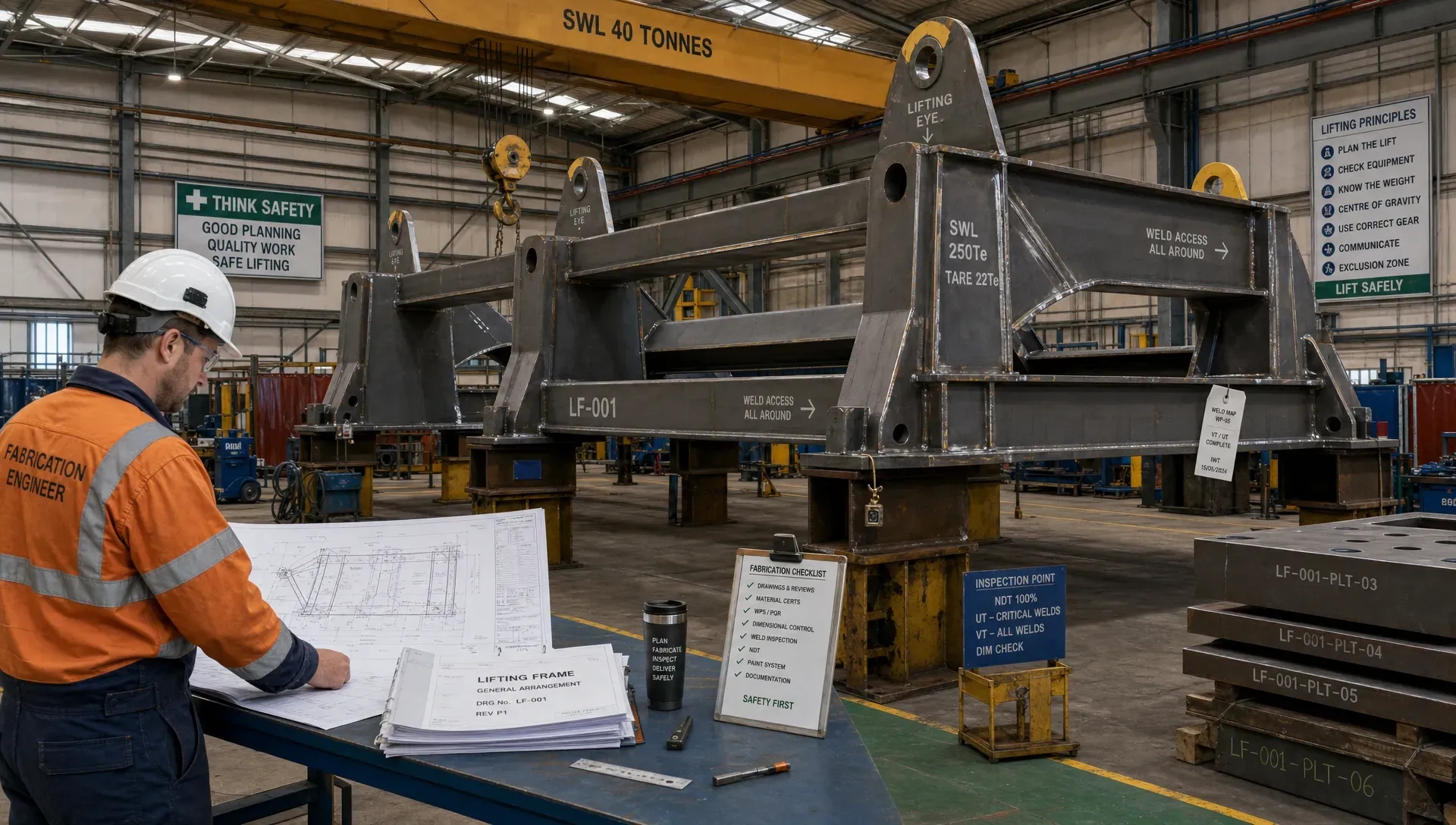
For example, a seafastening frame may be optimised by aligning load paths with vessel deck beams instead of adding large amounts of local steel. A retrofit support may be split into prefabricated subassemblies that can pass through vessel access routes and be installed during a short yard period. A lifting beam may use accessible weld details and inspection-friendly geometry rather than compact details that are difficult to qualify.
This is where engineering and detailing must stay connected. Fabrication drawings should not reinterpret engineering intent after the fact. They should translate verified loads, member sizes, weld requirements and interfaces into clear production information. For marine steelwork, disciplined steel detailing workflows help reduce uncertainty between design release and shop-floor execution.
Reducing steel, welding and handling effort
Reducing steel weight is not only a sustainability objective. It can also improve fabrication and installation performance. Less steel can mean fewer weld metres, fewer crane moves, shorter coating cycles, lower transport weight and simpler offshore handling. However, weight reduction must be based on sound engineering judgement, not arbitrary trimming.
The strongest opportunities usually come from better load-path definition. If the design sends load into known strong points, unnecessary secondary reinforcement can often be avoided. If local overstress is understood through FEM analysis, reinforcement can be targeted instead of spread across a larger area. If temporary loads are separated from permanent loads, the structure may avoid carrying design cases it will never experience in service.
The risk is under-engineering. Offshore structures must account for dynamic effects, fatigue, accidental loads, transport accelerations, installation tolerances and inspection requirements. The value lies in removing avoidable steel while keeping the safety case clear and traceable. That is why practical design engineering can reduce steel cost and approval risk when it is tied to verified load cases and realistic fabrication methods.
Designing installation into the structure
Installation is often treated as the next phase after fabrication. In offshore and maritime projects, it should be designed into the structure from the beginning. A structure that is easy to fabricate but difficult to lift, sea-fasten, align or bolt offshore can still become a major schedule risk.
Installation-aware engr design considers the lift path, centre of gravity, rigging geometry, crane capacity, vessel motions, deck layout, access, temporary supports, guide systems and removal sequence. It also considers what happens when conditions are not ideal. Offshore crews work with weather windows, vessel limitations, restricted access and dynamic loads. A design that depends on perfect alignment or excessive manual adjustment is not robust enough.
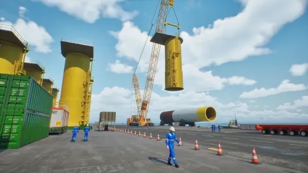
For heavy lift operations, this may involve designing padeyes, trunnions or lifting frames with clear load transfer into the main structure. For offshore wind foundation transport, it may involve grillages and seafastening that match vessel structure and installation sequence. For decommissioning, it may involve temporary strengthening and cut plans that keep lifted sections stable during removal.
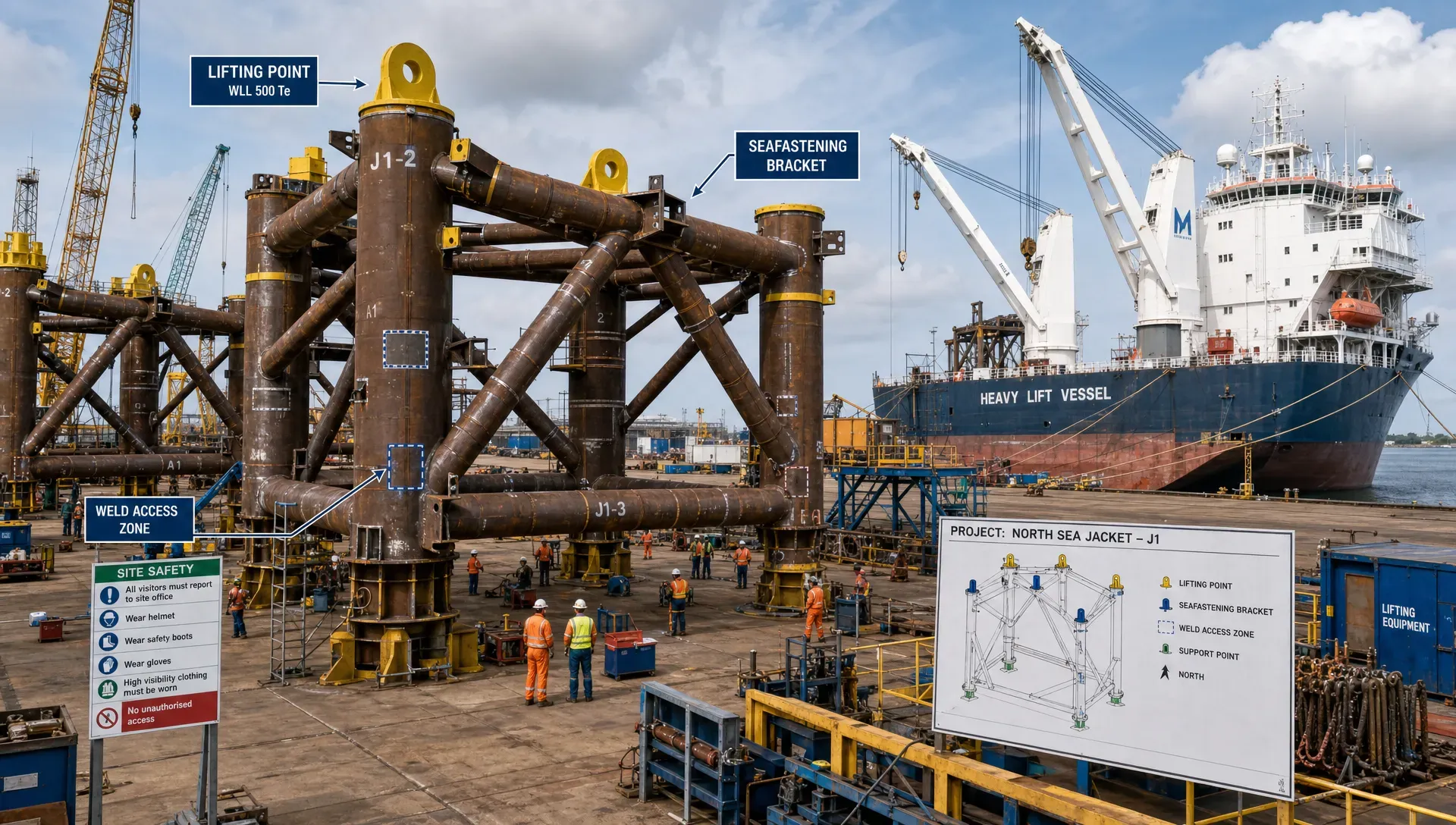
A good installation design also reduces offshore decision-making. The method statement, drawings, rigging plan, calculations and inspection requirements should tell the same story. If the offshore team has to resolve engineering ambiguity during mobilisation, the project has already absorbed unnecessary risk.
Approval readiness is part of constructability
Approval is not an administrative step at the end of design. It is part of constructability. A design that cannot be reviewed efficiently by MWS or class can delay fabrication release, vessel mobilisation or offshore execution.
Approval-ready engineering is traceable. The design basis links to the calculations. The calculations link to the drawings. The drawings show the details needed by fabrication and inspection. The installation procedure reflects the same load cases and limitations used in the engineering. This traceability is especially important for lifting arrangements, mooring reports, stability checks, seafastening design, temporary works and vessel modifications.
Incomplete documentation often creates review cycles that could have been avoided. Common issues include missing load combinations, unclear boundary conditions, unsupported allowable stresses, inconsistent weights, outdated general arrangements, or drawings that do not show critical welds and inspection requirements. Each comment may seem small, but the combined effect can be significant when a vessel, crane barge or yard slot is waiting.
Fusie Engineers supports projects with deliverables such as FEM calculations, motion analyses, lifting arrangements, mooring reports, stability checks, drawings and approval documentation. The practical value is not only producing documents, but making sure those documents are aligned with fabrication, installation and review requirements.
Designing for the real marine environment
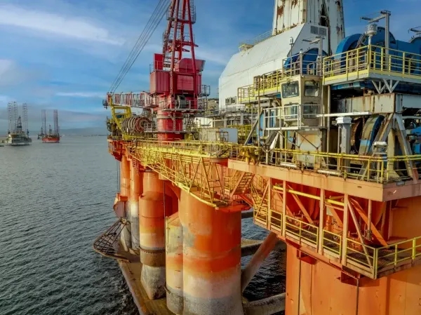
Marine engineering must account for an environment that is dynamic, corrosive and operationally constrained. Waves, currents, wind, vessel motions, tide windows, visibility, subsea access, fatigue and corrosion protection all influence how structures should be designed, installed and maintained.
That is also why project teams benefit from a broader respect for working oceans. Resources such as responsible ocean travel and diving guides are not engineering standards, but they are a useful reminder that underwater visibility, currents, access limitations and marine stewardship are real conditions, not abstract notes in a method statement. In engineering terms, those conditions become quantified design cases, access restrictions, inspection requirements and QHSE controls.
For vessel retrofits, the marine environment also includes the reality of legacy data. As-built conditions may differ from old drawings. Piping routes, cable trays, access hatches and structural members may have changed over years of operation. Strong engr design therefore includes verification, interface management and practical allowances for installation, rather than assuming that historic drawings are fully reliable.
Interface control prevents late changes
Many fabrication and installation problems begin at interfaces. A padeye may be structurally adequate but conflict with rigging access. A pipe support may fit the model but clash with a maintenance route. A grillage may carry the load but miss the strongest vessel structure below deck. A retrofit foundation may meet class requirements but require hot work in a location that disrupts other yard activities.
Interface control is not only a coordination task. It is an engineering task. The designer must understand which interfaces are fixed, which can move, and which require early decisions from operations, fabrication, the vessel owner or the approval party.
This is particularly important where naval architecture, structural engineering, marine operations and fabrication meet. Vessel stability affects lift planning. Mooring loads affect temporary structures. Underdeck structure affects grillage design. Fabrication sequence affects weld access and distortion control. Coating and inspection requirements affect detail geometry.
Good interface control reduces the number of surprises after release. It also gives project directors and engineering managers a clearer view of remaining risks before fabrication starts.
How this improves different project types
The same principles apply across offshore wind, maritime, shipbuilding, retrofit, decommissioning, dredging, green tech and traditional energy projects, although the technical emphasis changes.
- Offshore wind transport and installation: Grillage, seafastening, lifting tools and temporary structures must align with foundation geometry, vessel capacity, deck structure, transport accelerations and installation sequence.
- Vessel retrofit and piping: Engineering must manage legacy data, class constraints, access, spool prefabrication, support loads and clashes with existing systems.
- Heavy lift and decommissioning: Lift points, cut plans, temporary strengthening, centre of gravity control and rigging geometry must be verified before offshore execution.
- Ship design and marine engineering: Structural arrangements, outfitting, stability, maintainability and fabrication planning must be coordinated so the vessel can be built and operated efficiently.
In each case, the best outcomes come from bringing fabrication and installation knowledge into the design phase, not waiting for the yard or offshore team to discover problems later.
Questions to ask before releasing design to fabrication
Before issuing drawings for fabrication, engineering managers and project directors should test whether the design is ready for the realities of production and installation. A short review can prevent expensive rework.
Useful questions include:
- Has the design basis been agreed by engineering, operations, fabrication and approval stakeholders?
- Are load paths clear, and do they align with actual vessel or foundation structure?
- Can all critical welds be accessed, inspected and coated?
- Are lifting points, temporary supports and installation aids included in the design scope?
- Are weights, centres of gravity, tolerances and interface dimensions controlled?
- Does the approval package contain enough traceability for MWS or class review?
- Can the structure be transported, handled and installed within the planned schedule and equipment limits?
If the answer to any of these questions is uncertain, fabrication release may be premature. The cost of resolving uncertainty in design is usually far lower than resolving it after material is cut or a vessel is mobilised.
Frequently asked questions
How does engr design reduce fabrication rework? It reduces rework by aligning calculations, drawings, tolerances, weld details, material choices and interfaces before fabrication starts. This helps the workshop build from clear, verified information instead of resolving engineering uncertainty during production.
Why should installation be considered during the design phase? Offshore installation involves vessel motions, crane limits, rigging geometry, weather windows, access restrictions and safety controls. If these factors are ignored during design, the structure may require late modifications or create offshore execution risk.
What makes an engineering package approval-ready? An approval-ready package has a clear design basis, traceable calculations, consistent drawings, defined load cases, verified weights and centres of gravity, and documentation that matches the intended fabrication and installation method.
Can better design really reduce steel cost without compromising safety? Yes, when steel reduction comes from verified load paths, targeted reinforcement, realistic boundary conditions and appropriate analysis. The aim is not to make structures light at any cost, but to remove unnecessary material while preserving safety and approval confidence.
When should Fusie Engineers be involved in a project? The best time is before key fabrication, vessel selection or installation decisions are locked in. Early involvement allows engineering, buildability, class requirements and marine operations to be aligned before changes become expensive.
Bring fabrication and installation into the design phase
For offshore, maritime and energy projects, engr design should do more than produce drawings. It should reduce uncertainty, support approval, simplify fabrication and prepare the project for safe installation.
Fusie Engineers supports clients with offshore structural design, heavy lift engineering, ship design, vessel retrofits, piping design, marine engineering, steel detailing and technical visualisation. The team works with fabrication, installation and approval requirements in mind, helping project teams move from concept to execution with practical, buildable and traceable engineering.
If your project depends on safe lifting, efficient fabrication, class-ready documentation or reliable offshore installation, involving the right engineering partner early can reduce risk before it reaches the yard or the vessel.