Piping layout decisions that reduce clashes and rework onboard
2026-06-20
Onboard piping rarely fails because one pipe was drawn in the wrong place. Rework usually comes from a chain of small decisions: a valve positioned where it cannot be operated, a support added without checking underdeck structure, a spool length that cannot pass through an access hatch, or a penetration placed through a boundary that class will not accept without additional reinforcement.
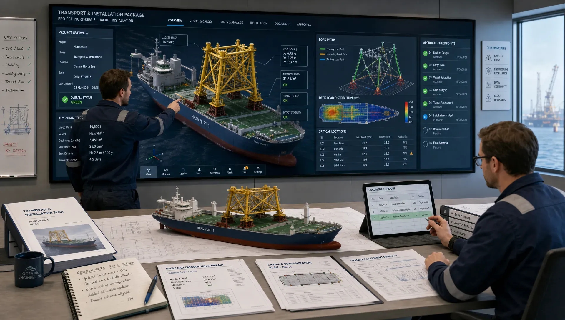
For vessel retrofits, ship repair, offshore support vessels, dredgers, FPSO modifications and newbuild marine projects, the piping layout is therefore not just a drafting activity. It is a coordination exercise between process requirements, naval architecture, structural design, class rules, yard installation methods and future maintenance. The better those interfaces are resolved early, the fewer clashes appear in the model, at the yard, or worse, during commissioning.
Why piping layout creates so much onboard rework
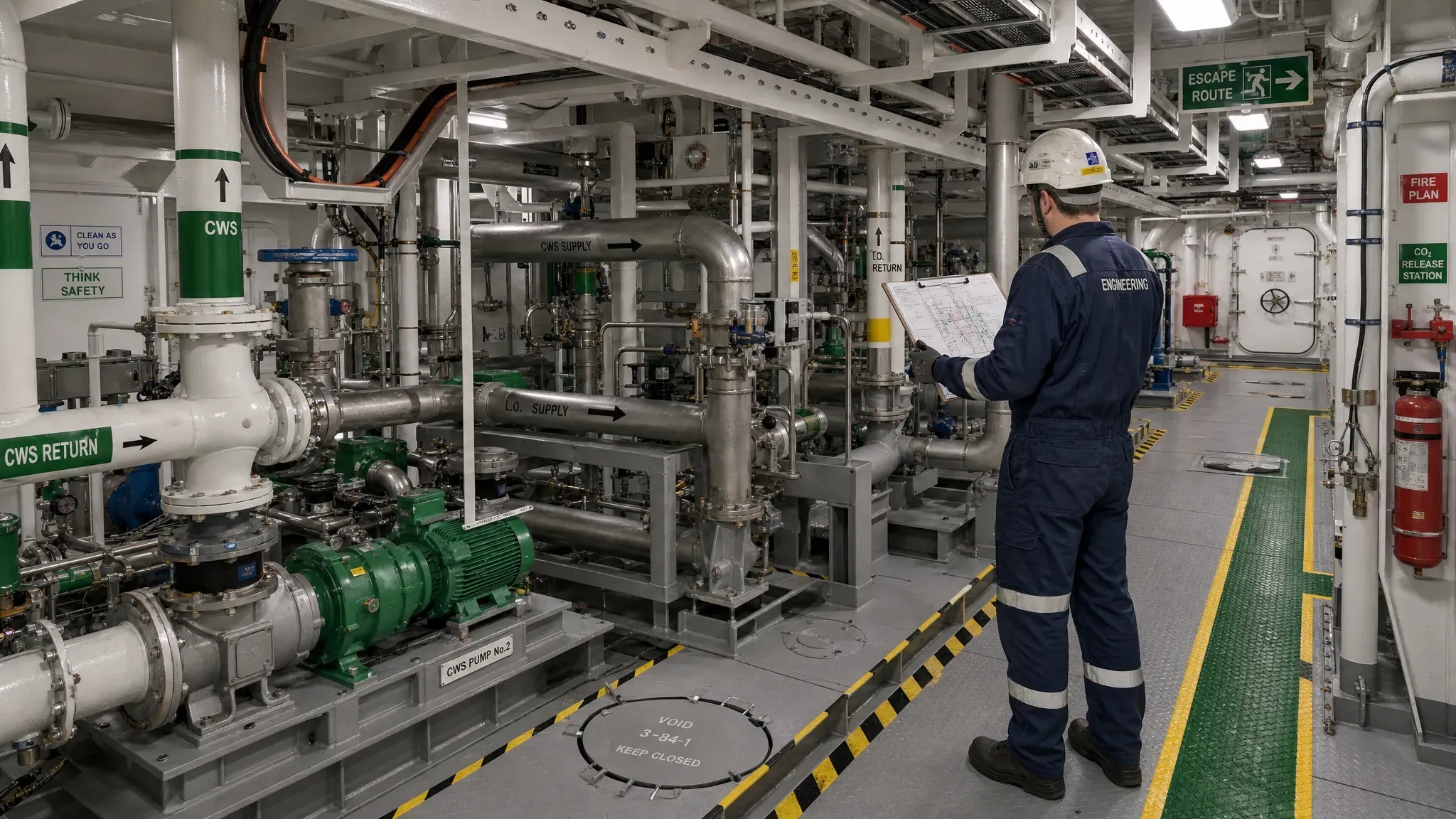
Marine spaces are dense. Engine rooms, pump rooms, voids, tanks, deckhouses and service corridors often carry piping, cable trays, ventilation ducts, access routes, escape routes, structural members and equipment removal paths within the same envelope. In a retrofit, the layout is even harder because the design team must work around existing structure, old penetrations, undocumented modifications and operational limitations.
A technically correct pipe route can still become expensive if it is hard to fabricate or install. For example, a short route through a congested area may reduce material length, but it can increase hot work, require difficult overhead welding, block access to existing valves, or force late changes to cable trays and supports. A slightly longer route with clearer access and simpler supports may be cheaper and safer overall.
The goal is not only to avoid hard clashes in a 3D model. A good piping layout should also reduce soft clashes, installation clashes, maintenance clashes and approval clashes. That means checking clearances, support loads, isolation philosophy, accessibility, drainage, venting, class boundaries and construction sequence before the yard starts cutting steel.
Start with a controlled design basis
Piping layout decisions become unreliable when the design basis is vague. Before routing starts, the engineering team should define the system purpose, design pressure, design temperature, pipe class, corrosion allowance, insulation requirements, fluid properties, slope requirements, hazardous area constraints and applicable class rules. This is also the stage to confirm whether the work is a like-for-like replacement, a capacity upgrade, a new system integration or part of a wider conversion.
For vessel retrofit scopes, the design basis should include the operational condition of the vessel during the work. Can the vessel be taken out of service? Are systems isolated by area or by function? Will installation happen afloat, in dry dock, alongside, or during a phased yard stay? These decisions affect spool sizes, tie-in locations, temporary supports, testing sequence and the amount of prefabrication that is realistic.
This is why piping work should be aligned with the wider retrofit strategy. Early checks similar to those used in vessel retrofit engineering that avoids class and yard delays help prevent a piping package from moving faster than the structural, class or installation information it depends on.
Verify the vessel before trusting the drawings
Legacy drawings are useful, but they are not always reliable. Vessels accumulate modifications over years of operation, emergency repairs, owner upgrades and yard-specific changes. A drawing may show an open routing corridor that is now occupied by a cable tray, a local stiffener, an added bracket, a fire damper, an undocumented drain line or a piece of equipment that was installed after delivery.
Good piping layout work starts with verification. This can include laser scanning, targeted manual measurements, photographic surveys, opening-up checks, equipment tag verification and comparison between existing drawings and the actual vessel. For critical areas, the team should confirm not only geometry, but also structural condition, coating restrictions, access limitations and hot-work constraints.
The biggest value of as-built verification is not that it produces a prettier model. It gives engineers confidence to make layout decisions that the yard can execute. It also reduces the risk of issuing drawings that look complete but collapse when a fitter stands in front of the actual space.
Set a routing hierarchy before modelling every line
In congested compartments, not every discipline can have the shortest or cleanest route. A routing hierarchy makes priorities clear before detailed modelling starts. Critical systems, large-bore lines, gravity drains, fire mains, fuel systems, hydraulic lines, cable trays, HVAC ducts and access routes all compete for space. If the hierarchy is not defined, the model may become a sequence of local compromises that creates bigger problems later.
Large and stiff systems usually need earlier reservation of space because they are harder to move later. Gravity systems need slope and low-point drainage. Hot lines may need insulation and separation. Fuel, hydraulic and hazardous systems may require routing decisions linked to fire safety and class requirements. Maintenance zones around filters, strainers, valves and pumps must be protected, not filled with secondary pipework.
This kind of spatial planning is not limited to marine projects. In building fit-outs and refurbishments, experienced contractors also coordinate plumbing, structure, access and finishes before work starts, which is one reason clients often rely on specialist home renovation contractors in Dubai for complex space planning. Onboard, the same principle applies under tighter constraints, with stricter safety, class and operational consequences.
A clear hierarchy helps the design team answer practical questions quickly. Which service moves if a pipe and cable tray clash? Which system has priority at a bulkhead penetration? Which access zone is protected? Which route must remain removable for future equipment overhaul? These decisions should be agreed before the model review becomes a debate over hundreds of individual clashes.
Coordinate supports, penetrations and structure early
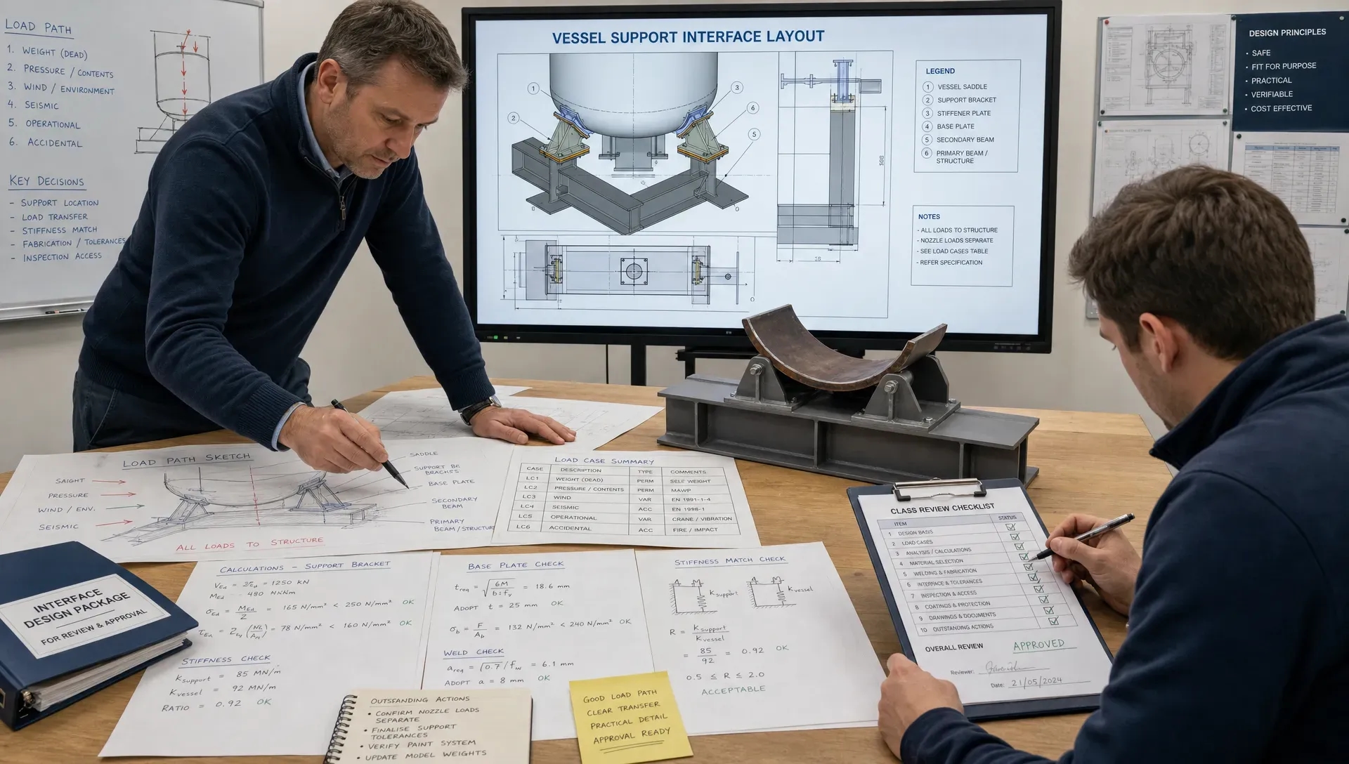
A pipe does not only occupy space along its centreline. It transfers loads into the vessel through supports, guides, anchors and penetration details. These loads may include static weight, fluid weight, insulation weight, thermal movement, vibration, sloshing, vessel motion and occasional loads from pressure testing or operational transients.
If support locations are selected late, the layout may force the yard to add brackets in weak, awkward or inaccessible places. Supports may land on thin plating, unsupported panels, insulation zones, removable hatches or structure that cannot accept the load without reinforcement. In dynamic marine environments, support decisions also affect fatigue, vibration and noise.
Penetrations need the same early attention. Bulkhead and deck penetrations may affect watertight integrity, fire boundaries, tank boundaries, blast considerations, coating systems and class approval. A route that appears simple in the model can become difficult if it requires a new penetration through a protected boundary or a reinforcement detail that conflicts with existing structure.
This is where piping layout should be coordinated with structural engineering, not handed over after routing is complete. The same buildability logic discussed in structural engineering choices that improve buildability offshore applies to marine piping: simple load paths, practical fabrication details and early interface control reduce rework.
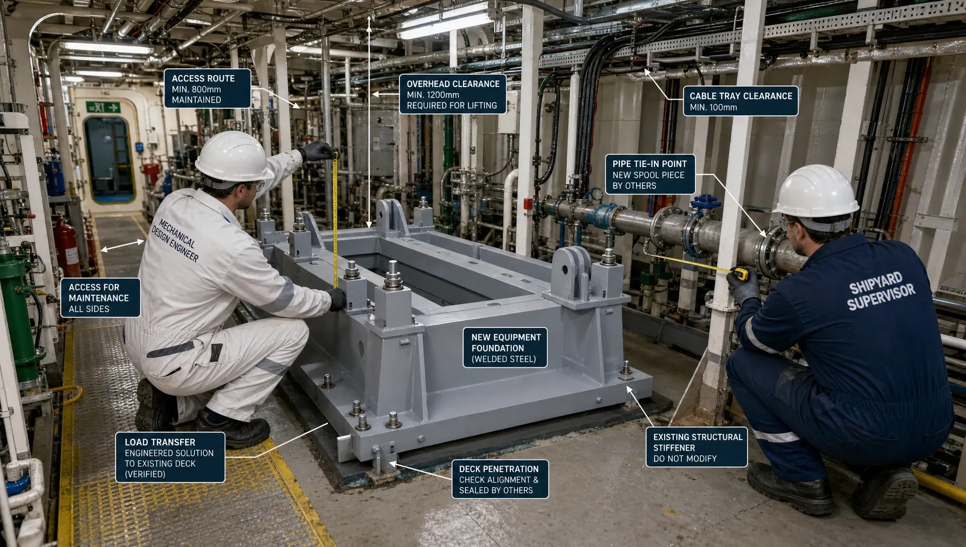
A detailed marine engine room section showing coordinated pipe routes, valves, supports and access clearances around pumps, structural frames and deck penetrations onboard a vessel, with the view looking diagonally across the machinery space toward the far bulkhead.
Design for installation, not only for the 3D model
A clash-free model does not guarantee a buildable piping system. The yard still needs to bring spools onboard, move them through openings, align them in position, weld or bolt them safely, test them and reinstate coatings or insulation. If these practical steps are ignored, rework simply moves from the design office to the vessel.
Spool philosophy is a major layout decision. Long spools may reduce field welds, but they can be impossible to transport through companionways, hatches or congested engine room routes. Short spools may be easier to handle, but they increase weld count, inspection time and documentation. Flanged connections may improve maintainability, but add weight, cost and space requirements. The right answer depends on access, yard capability, material, system criticality and inspection requirements.
Weld access should also be checked early. A pipe route that leaves no room for fit-up, welding, non-destructive testing or coating repair will create delays even if it passes through the model without clashes. Overhead welds, tight corners and locations behind equipment often increase labour hours and quality risk.
For offshore or high-mobilisation-cost projects, installation logic can be as important as material quantity. Saving a few metres of pipe is rarely worthwhile if the route creates extra hot work, delayed testing, scaffold congestion or late approval queries. The best piping layouts are often those that balance compact routing with safe installation and predictable yard execution.
Keep valves, instruments and access points usable
Piping layout should protect the people who operate and maintain the vessel. Valves, strainers, filters, drain points, sample points, pressure gauges, transmitters and local panels need clear access. They also need to be located where operators can use them safely, without standing on pipework, leaning across hot surfaces, blocking escape routes or working above rotating equipment.
Maintenance access is easy to compromise because the model may show a nominal clearance that looks acceptable from one viewpoint. In practice, the technician may need space for tools, lifting aids, insulation removal, bolting, gasket replacement or component extraction. A valve handwheel may clear a beam, but still be unusable if it is positioned too high, too close to another service, or behind a removable panel that cannot be opened after adjacent pipework is installed.
Equipment removal paths deserve special attention. Pumps, heat exchangers, filters and package units may need future overhaul. If piping is routed across lifting eyes, withdrawal zones or removable covers, the vessel owner inherits a maintenance problem long after the yard scope is complete.
Use model reviews as engineering gates
Model reviews should not be treated as cosmetic walkthroughs. They are decision gates where the team confirms that the piping layout is safe, buildable, maintainable and ready for the next stage of engineering. For complex vessel scopes, the review should involve piping, structural, naval architecture, electrical, HVAC, operations, yard representatives and, where relevant, class or the Marine Warranty Surveyor.
The review process should distinguish between different clash types:
- Hard clashes, where pipework physically intersects structure, equipment, cable trays or other services.
- Soft clashes, where required clearance for operation, inspection, insulation, heat, vibration or removal is missing.
- Installation clashes, where the route cannot realistically be fabricated, transported, fitted, welded, tested or coated.
- Approval clashes, where a route affects class boundaries, hazardous area philosophy, fire protection, watertight integrity or safety documentation.
Digital tools can speed up this process, but only if the data is controlled. Revision status, survey confidence, hold areas, class comments and yard feedback must be visible to the team. Otherwise, automated clash lists can create noise without resolving the engineering risks. A structured approach to engineering software that speeds review without losing control helps teams use digital models as decision tools rather than isolated design files.
Control change after the layout is frozen
Late changes are normal in marine projects. Equipment delivery data changes, yard surveys reveal surprises, class asks for clarification, operators request access improvements, or adjacent scopes move. The problem is not change itself. The problem is uncontrolled change after drawings, material take-offs, supports and installation plans have already been issued.
A practical piping change process should show what changed, why it changed, what systems are affected and whether the change impacts stress, support loads, penetrations, class approval, testing, materials or installation sequence. Every modification should be checked against the 3D model, drawings, isometrics, support details, bill of materials and commissioning documentation.
This discipline is especially important when multiple contractors work onboard at the same time. A small routing change by one party can block another contractor’s cable tray, ventilation duct, inspection access or structural bracket. Clear interface management prevents one solved problem from creating several new ones.
Piping layout checklist for reducing onboard rework
Before issuing piping drawings for fabrication or installation, the engineering team should be able to answer a focused set of questions:
- Has the design basis been agreed, including class rules, pipe classes, operating conditions and testing requirements?
- Has the existing vessel geometry been verified in critical routing areas?
- Are large-bore, gravity, hazardous, hot and maintenance-critical systems prioritised in the routing hierarchy?
- Are valves, instruments, filters, drains and vents accessible for safe operation and maintenance?
- Have supports, guides, anchors and penetrations been coordinated with structural capacity and class boundaries?
- Can spools be transported onboard, positioned, welded, inspected, coated and tested using realistic yard methods?
- Are removal paths for equipment and future maintenance zones protected?
- Has every late change been checked against drawings, material take-offs, supports, class comments and installation sequence?
This checklist will not remove every project surprise. It does, however, force the right engineering conversations before steel is cut, pipe is ordered and mobilisation dates become difficult to move.
Frequently asked questions
What is the main cause of piping clashes onboard? The main cause is usually incomplete interface control, not poor modelling alone. Piping clashes often come from unverified as-built data, late equipment changes, unclear routing priorities, missing access zones, or support and penetration details that were not coordinated with structure and class requirements.
Why is piping layout harder in vessel retrofit projects? Retrofit work must fit around existing structure, systems, access limitations and undocumented vessel changes. The design team also has to consider yard sequence, isolation, hot-work restrictions, class approval and whether the vessel remains partly operational during the modification.
When should class requirements be considered in piping layout? Class requirements should be considered from the design basis stage. Waiting until the layout is complete can lead to rework around penetrations, fire boundaries, watertight integrity, materials, testing, supports and access for inspection.
How can 3D modelling reduce onboard piping rework? 3D modelling helps when it is based on verified vessel data and used in structured reviews with all relevant disciplines. It can identify hard clashes, clearance issues, installation problems and maintenance conflicts before fabrication begins.
Is the shortest pipe route always the best option? No. The shortest route may increase welding difficulty, support complexity, access problems or class approval risk. A slightly longer route can be better if it improves buildability, maintainability, testing and overall project certainty.
Need piping layout support for a vessel or offshore project?
Fusie Engineers supports vessel retrofits, piping design, marine engineering, ship design, offshore structural design and heavy lift engineering with a practical focus on safety, buildability and approval readiness. Our teams work across maritime, offshore wind, energy, decommissioning and retrofit scopes where clear interfaces and reliable documentation are essential.
If your project needs piping layout decisions that reduce clashes, yard rework and approval risk, speak with Fusie Engineers about support from concept and survey review through detailed engineering, drawings and installation-ready documentation.