Heavy lift engineering checks that prevent offshore delays
2026-06-25
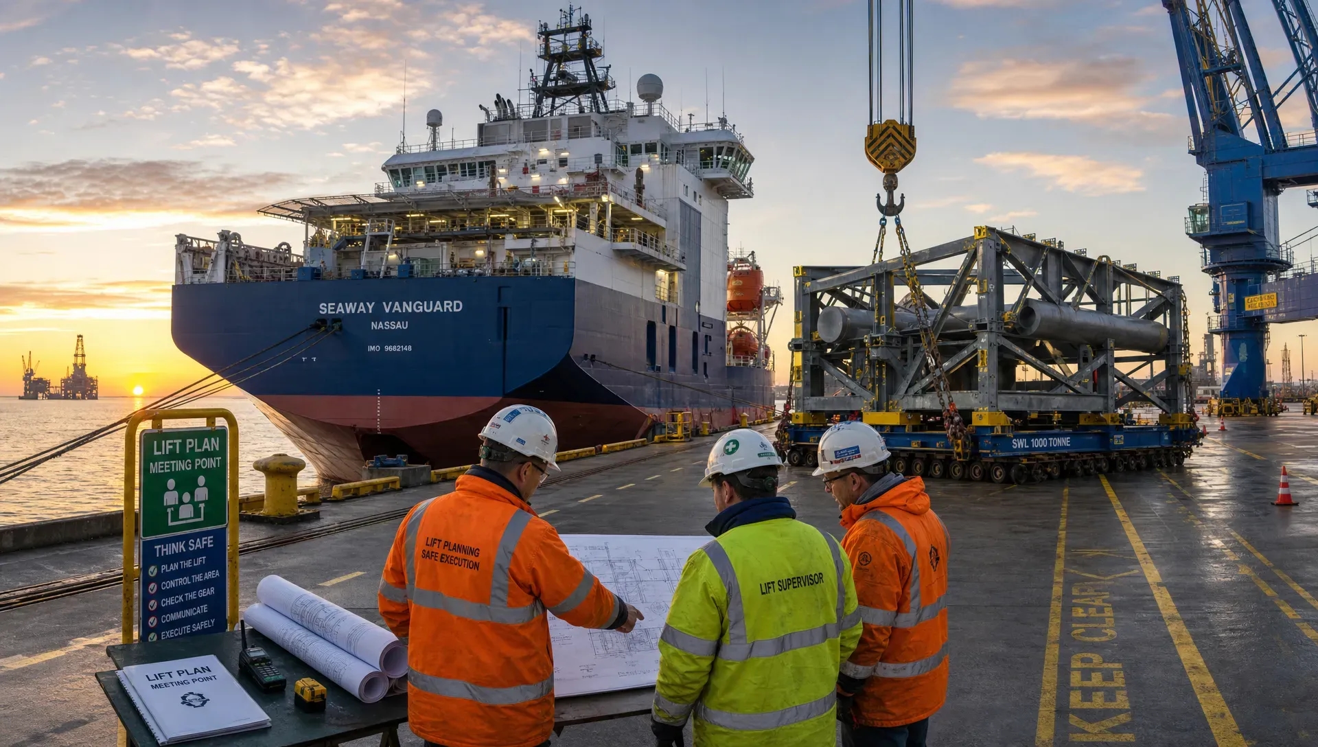
Offshore delays are expensive because they rarely affect one activity in isolation. A missing calculation, late MWS comment, underestimated rigging weight or unclear lift point interface can hold a vessel alongside, push a weather window, delay fabrication or force a last-minute redesign. In heavy lift operations, schedule certainty is not created offshore. It is created through disciplined engineering checks long before mobilisation.
Heavy lift engineering is often discussed in terms of crane capacity and rigging selection, but the checks that prevent delays go further. They connect structural design, vessel capability, seafastening, fabrication, class requirements, transport motion, installation sequencing and site constraints into one controlled package. If one part of that chain is weak, the lift may still look feasible on paper while the project becomes difficult to approve, fabricate or execute.
For project directors, lead engineers, marine contractors and offshore wind developers, the objective is not only to design a safe lift. It is to deliver a lift package that is safe, buildable, reviewable and ready for offshore execution.
Why offshore delays often begin in early engineering
Most offshore lifting delays are not caused by a single dramatic failure. They usually come from small gaps that accumulate across interfaces. A centre of gravity changes after late design updates. A grillage is strong enough globally but clashes with underdeck structure. A padeye calculation is complete, but the weld detail is difficult to inspect. A lift procedure assumes a rigging geometry that does not match the available hook height. A Marine Warranty Surveyor requests clarification, but the supporting documentation is scattered across several revisions.
These issues create delay because offshore operations have little tolerance for uncertainty. Vessels, cranes, crews, ports and weather windows are scheduled around a narrow execution sequence. Once mobilisation starts, even a modest design change can trigger rechecking, fabrication modification, document reissue and renewed approval.
A useful heavy lift engineering process therefore works backwards from execution. It asks what could stop the operation at the quay, during transport, at the lift site, during MWS review, during class approval or during fabrication. The checks below are aimed at those stopping points.
Start with a controlled design basis
A controlled design basis is the foundation of an approval-ready lift package. Without it, engineering teams may calculate against different assumptions, and reviewers may challenge the basis rather than the details. This is especially risky when structural engineers, naval architects, vessel owners, fabricators, crane suppliers and marine warranty teams are working in parallel.
The design basis should define the object being lifted, the operational phases, governing standards, environmental limits, vessel data, crane data, rigging arrangement, load factors, acceptance criteria and documentation hierarchy. It should also define which information is preliminary and which is frozen.
Design basis item | Why it prevents delay | Typical issue if missed
---
Lift object weight and centre of gravity | Confirms crane capacity, rigging loads and structural reactions | Late weight growth invalidates lift calculations
Crane vessel data | Confirms hook height, outreach, capacity curve and allowable sidelead or offlead | Lift is feasible structurally but not operationally
Environmental limits | Aligns design cases with weather window and vessel motions | Procedure cannot be accepted for actual site conditions
Governing standards and approval route | Gives reviewers a clear basis for acceptance | MWS or class comments arrive late and require rework
Interface drawings and as-built data | Confirms fit-up, support locations and vessel structure | Grillage or seafastening clashes during fabrication or mobilisation
A strong design basis also supports change control. Offshore projects often evolve, particularly during vessel retrofit, decommissioning, dredging, offshore wind foundation installation and heavy civils marine works. The issue is not change itself. The issue is uncontrolled change that does not trigger the right rechecks.
Verify the complete load path, not only the lifted object
A lift is a temporary structural system. The load path runs from the object through lift points, welds, local stiffeners, spreaders, slings, shackles, crane hook, crane structure, vessel, grillage, seafastening and support foundations. Delays occur when engineering checks focus on one component while overlooking how the complete system behaves.
For example, a padeye may pass a standalone check, but the supporting plate may be too flexible. A spreader bar may be adequate in axial compression, but the rigging geometry may introduce bending. A grillage beam may pass global utilisation, but the reaction may land between vessel frames. These are not theoretical issues. They directly affect fabrication scope, NDT access, class review and offshore readiness.
Good heavy lift engineering checks therefore include both global and local verification. Global checks confirm overall stability, crane load, object strength and vessel capacity. Local checks confirm stress concentrations, plate buckling, weld sizing, bearing, pin holes, trunnions, brackets, doubler plates and underdeck reinforcement.
This system view is also why heavy lift engineering should not be treated as isolated calculation work. The engineering team needs to understand fabrication tolerances, rigging behaviour and marine operations. For a broader explanation of this integrated approach, Fusie Engineers has covered the full-system fundamentals of heavy lift engineering in more detail.
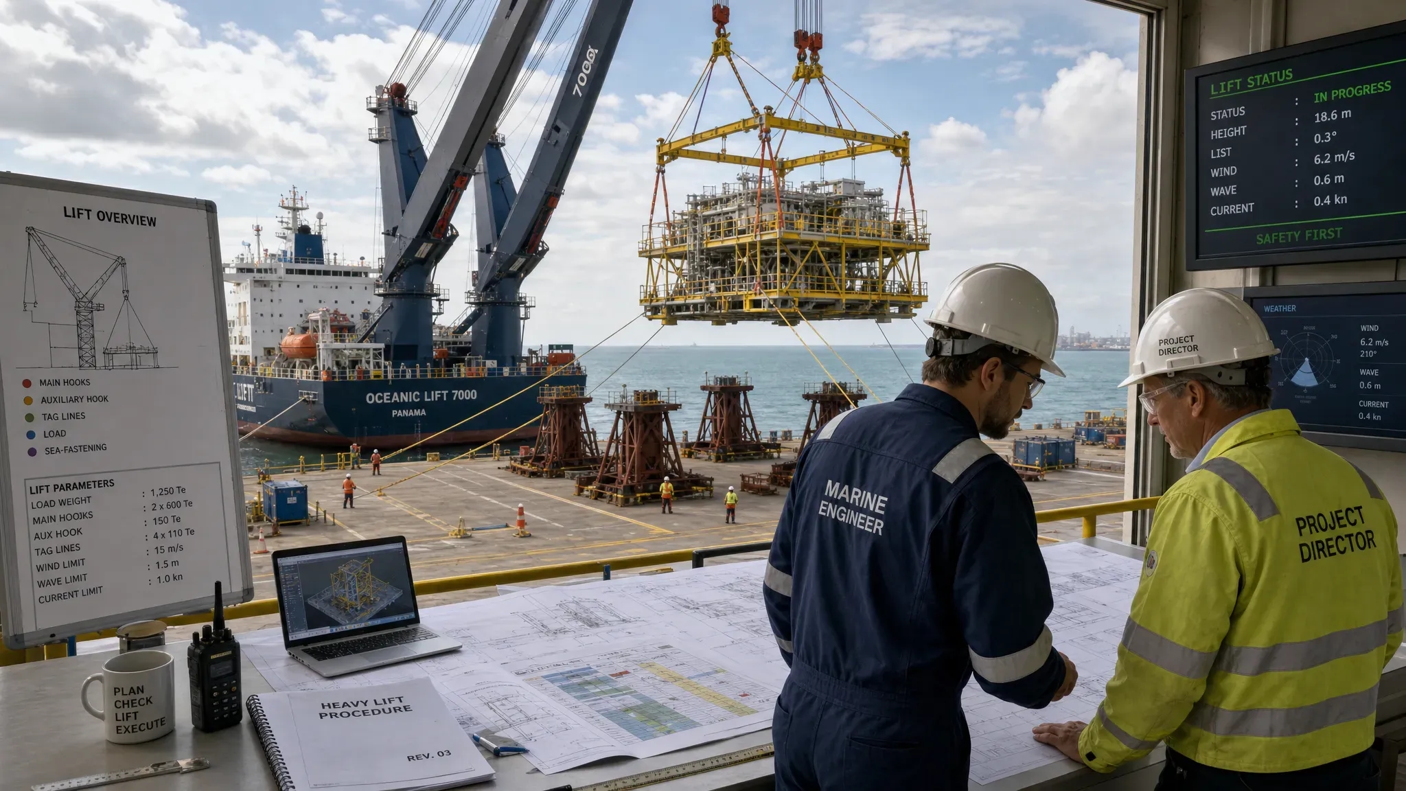
Check crane capacity against the real lift configuration
Crane capacity is not just a number from a chart. It depends on radius, hook height, rigging weight, dynamic factors, vessel heel and trim, crane configuration, allowable motions, slew limitations and the operational sequence. A lift that appears acceptable at concept stage can become constrained once the detailed rigging arrangement is added.
The most useful crane and rigging checks ask practical execution questions:
- Can the crane achieve the required radius with the selected vessel position and object orientation?
- Is there enough hook height after allowing for slings, spreaders, shackles, lift points and clearance?
- Has rigging self-weight been included in the crane load?
- Are sling angles within allowable limits for both rigging and lifted structure?
- Are sidelead and offlead within crane and procedure limits?
- Can the object be landed without creating an uncontrolled load transfer?
The answers should be documented in a way that operations teams can use, not only in calculation files. Lift plans, arrangement drawings, rigging schedules and step-by-step procedures must match the assumptions used in the calculations. If they do not, MWS comments and offshore queries are likely.
Control weight and centre of gravity changes
Weight control is one of the most important delay prevention disciplines in heavy lift projects. Small changes can have large effects because they influence crane utilisation, sling loads, lift point reactions, vessel stability, grillage design and transport accelerations.
The centre of gravity is particularly critical. A small CoG shift can create sling load imbalance, increase local lift point forces or require modified rigging. In multi-point lifts, skew load effects and fabrication tolerances should be considered early, especially where structures are large, flexible or irregular.
A practical weight control process should define the source of weight data, maturity level, contingency, update frequency and approval responsibility. This is vital for vessel retrofit and decommissioning projects, where legacy drawings may not reflect actual installed equipment. It is also important for shipyard works and offshore wind scopes where late attachments, access platforms, sea fastenings or temporary work items can change the lift configuration.
When information is uncertain, assumptions must be visible. Hidden assumptions create late surprises. Visible assumptions can be challenged, measured or mitigated before mobilisation.
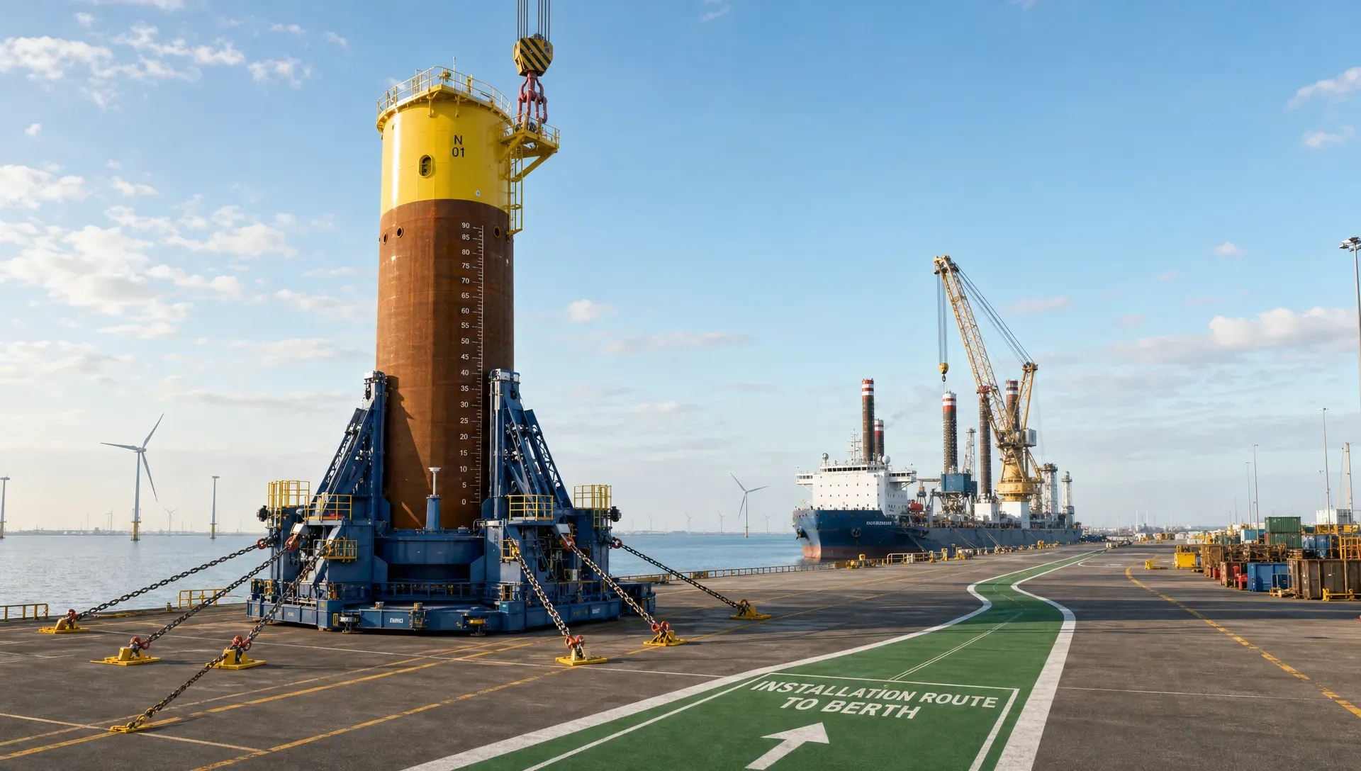
Design seafastening and grillages for transport, installation and removal
Seafastening and grillages often sit between structural design and marine operations. They must withstand transport accelerations, distribute loads into the vessel, allow efficient fabrication, avoid clashes, support safe installation and be removable without excessive hot work offshore or in port.
A common cause of delay is designing temporary steel only for strength, without checking buildability and vessel integration. A heavy grillage with complex weld details may pass calculations but increase fabrication time. A seafastening bracket may be structurally efficient but difficult to access for welding, inspection or cutting. A support reaction may be acceptable in the grillage but not in the underdeck structure.
This is where practical structural engineering has a direct schedule impact. Clear load paths, sensible plate thicknesses, accessible welds and fabrication-friendly details can reduce both steel weight and rework. Fusie Engineers discusses this in the context of structural engineering choices that improve buildability offshore, which is highly relevant to heavy lift temporary works.
Check vessel capability and marine operation constraints
Heavy lift engineering cannot be separated from marine engineering. Vessel behaviour affects crane loads, stability, deck reactions, mooring loads and installation feasibility. For floating lifts, dynamic amplification, motions, heel, trim and ballasting sequence can become governing factors. For quayside lifts, deck capacity, underdeck framing, quay bearing capacity and access constraints can be equally important.
Vessel checks should consider the full operation, not only the lift moment. This includes load-out, transport, standby, installation, possible waiting on weather, emergency conditions and demobilisation. For offshore wind, maritime, oil and gas, decommissioning and renewable energy projects, each phase may have different governing constraints.
Mooring and station-keeping checks are also important when the lift is sensitive to vessel position. If the vessel cannot maintain the required position within operational limits, the structural design may be acceptable but the installation method may not be. The same applies to clearances around jackets, foundations, topsides, quay walls, dredging equipment or adjacent vessels.
This is why integrated marine and structural review is valuable. The engineering package should connect vessel capability, lift geometry, structure strength and operational limits. Fusie Engineers has also explained how marine engineering cuts risk in offshore projects, particularly where vessel behaviour and temporary structures interact.
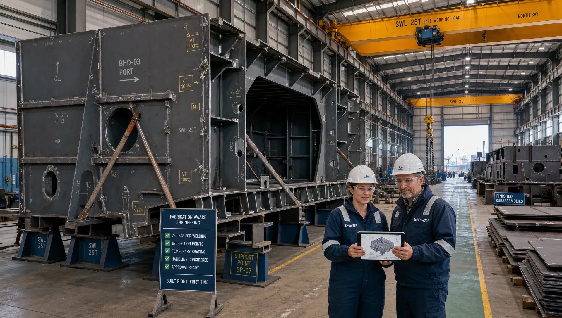
Build fabrication readiness into the engineering checks
A design that is technically correct but difficult to fabricate can still delay the project. Fabrication readiness checks should begin before drawings are issued for construction, not after the workshop raises queries.
Key questions include whether welds are accessible, whether plate thicknesses are realistic, whether tolerances are achievable, whether lifting attachments can be fitted without distortion, whether NDT can be performed, and whether the fabrication sequence matches the installation sequence. These checks are particularly important for temporary works that must be fabricated quickly and installed during a short mobilisation period.
Steel detailing also matters. Shop drawings should give fabricators clear information on dimensions, welds, cut-outs, bevels, material grades, fit-up and inspection requirements. Ambiguity creates requests for information, and requests for information create delay when vessels and crews are already scheduled.
Buildability checks are also a cost control measure. Reducing unnecessary steel, avoiding complex welds and simplifying connections can shorten fabrication time while maintaining safety. In many heavy lift scopes, the fastest solution is not the lightest possible theoretical structure. It is the most practical structure that meets the design requirements, can be approved and can be built reliably within the project schedule.
Prepare for MWS and class review from the start
Marine Warranty Surveyor and class comments often cause delay when documentation is incomplete, inconsistent or difficult to trace. The technical design may be sound, but reviewers need a clear approval package. They must understand the design basis, assumptions, load cases, acceptance criteria, calculations, drawings, procedures and responsibilities.
A review-ready heavy lift package typically includes the following elements.
Deliverable | Review purpose | Delay reduced
---
Design basis and load case summary | Shows what has been checked and why | Avoids debate over assumptions late in the programme
Structural calculations or FEM report | Demonstrates utilisation, buckling, weld and local checks | Reduces repeated technical clarification
Rigging and lifting arrangement drawings | Confirms geometry, equipment and clearances | Prevents mismatch between calculation and operation
Seafastening and grillage drawings | Shows load transfer into vessel or transport structure | Reduces fabrication and vessel integration queries
Marine operation procedure | Connects engineering limits to execution steps | Helps MWS assess operational feasibility
Weight and CoG report | Confirms lift inputs and change control | Prevents late recalculation due to unclear mass data
Approval readiness is not only about producing more documents. It is about producing consistent documents. Drawing revisions must match calculation revisions. Procedures must use the same environmental limits as the design basis. Equipment certificates must match the rigging schedule. If one document changes, the effect on the rest of the package should be traceable.
For projects involving DNV, Lloyd’s Register, ABS or other class societies, early alignment on the approval route is also important. The required checks for a vessel modification, temporary seafastening, lifting appliance interface or structural retrofit may differ depending on class scope and project context.
Use digital tools, but keep engineering control
Digital workflows can speed up heavy lift engineering, especially when teams are working across locations and disciplines. Shared models, controlled document systems, calculation templates, visual review tools and 3D coordination can reduce errors and improve communication. Technical animation and visualisation can also help explain complex lifting sequences to clients, site teams and QHSE stakeholders.
However, tools do not replace engineering control. A model is only useful if the inputs are correct. A checklist is only valuable if responsibilities are clear. A visualisation is only reliable if it reflects the approved method. Teams comparing supporting software for documentation, file control or visual communication can use independent resources such as digital tool guides to shortlist options, but the engineering team must still define the process, assumptions and approval logic.
The most effective digital workflows support traceability. They help the team see which weight revision was used, which drawing informed the FEM model, which procedure revision was reviewed by MWS and which site change triggered a recalculation. This is especially valuable when internal teams, external engineers, fabricators, vessel owners and approval bodies are working under tight deadlines.
A practical delay prevention checklist
Before mobilisation, the engineering lead should be able to confirm that the following checks are complete and aligned across the project package:
- The design basis is approved or clearly frozen for the current engineering stage.
- Lift object weight, CoG and contingency are documented and controlled.
- Crane capacity is checked for actual radius, hook height, rigging weight and operational limits.
- Lift points, rigging, spreaders and supporting structure are verified as one load path.
- Grillage and seafastening loads are checked against vessel deck and underdeck capacity.
- Transport accelerations, vessel motions and environmental limits are reflected in the design.
- Stability, ballast, mooring and positioning constraints are aligned with the lift procedure.
- Fabrication drawings are clear, buildable and consistent with calculations.
- Weld access, NDT access, tolerances and removal requirements have been reviewed.
- MWS and class deliverables are complete, consistent and revision controlled.
- Operational procedures match the engineering assumptions and approved limits.
- Contingency cases, hold points and change control responsibilities are defined.
This checklist is not a substitute for project-specific engineering judgement. It is a way to expose gaps before those gaps become offshore delays.
Where Fusie Engineers adds value
Fusie Engineers supports heavy lift, offshore structural design, marine engineering, ship design, vessel retrofit, piping and steel detailing scopes across maritime, renewable energy and traditional energy projects. For heavy lift work, that means connecting calculations with execution reality: vessel constraints, fabrication sequence, class expectations, MWS review, rigging behaviour, transport loads and offshore installation limits.
The practical value is not only extra engineering capacity. It is the ability to develop lift-related structures, seafastening, grillages, custom tools and approval documentation with safety, buildability and schedule in mind. That may include FEM calculations, lifting arrangements, motion analyses, mooring reports, stability checks, drawings and technical reports, depending on the project scope.
For contractors and project teams facing tight mobilisation dates, the right engineering support can reduce uncertainty before steel is cut and before vessels are committed. That is where delay prevention becomes measurable: fewer late comments, fewer fabrication changes, clearer offshore procedures and better alignment between engineering, operations and approval stakeholders.
Frequently asked questions
What is the most common engineering cause of offshore lifting delays? A common cause is misalignment between calculations, drawings and the actual operation. For example, the lift calculation may use one weight, rigging geometry or environmental limit while the procedure or fabrication drawings show another. This creates late review comments and can require rechecking.
When should heavy lift engineering checks start? They should start during concept and method development, before fabrication and mobilisation decisions are locked in. Early checks on weight, CoG, crane capacity, vessel structure, seafastening and approval route help prevent expensive changes later.
How do MWS requirements affect heavy lift engineering? MWS review requires clear evidence that the operation is safe and controlled. The package should include a design basis, calculations, drawings, procedures, equipment details, weather limits and traceable assumptions. Incomplete or inconsistent documentation can delay approval even when the design itself is sound.
Why are seafastening and grillage checks important for lift schedules? Seafastening and grillages connect the lifted or transported structure to the vessel. If they clash with vessel structure, overload underdeck framing or require difficult fabrication, they can delay mobilisation. Early checks help make the design both strong and buildable.
Can technical visualisation help prevent offshore delays? Yes, when it is based on the approved engineering method. Animations and visual sequences can help stakeholders understand rigging, clearances, lifting steps, exclusion zones and hold points. They are especially useful for QHSE briefings, tender explanations and complex marine operations.
Need heavy lift engineering support before mobilisation?
If your project involves a complex lift, vessel interface, seafastening scope, grillage design, retrofit, transport operation or MWS approval package, early engineering checks can protect the schedule as much as the structure.
Fusie Engineers can support your team from concept checks and calculations through detailed design, drawings and approval documentation. Contact Fusie Engineers to discuss how practical, approval-ready heavy lift engineering can reduce offshore delay risk on your next project.