




How a mechanical design engineer solves retrofit interfaces
2026-07-11
Retrofit projects rarely fail because one new component is impossible to design. They fail when that component cannot be integrated cleanly into the vessel, plant or offshore asset that already exists. A pump skid may be technically correct, a lifting frame may pass calculation, and a piping spool may look efficient in isolation. The real question is whether all of it fits, connects, transfers load safely, can be installed within the yard window, and can be approved without late redesign.
That is where a mechanical design engineer adds value beyond modelling parts or producing drawings. In retrofit work, the role is to resolve interfaces between new and existing systems, between disciplines, and between design assumptions and site reality. For shipyards, vessel owners, offshore contractors and EPC teams, that interface work directly affects safety, fabrication cost, class approval and schedule certainty.
Retrofit interfaces are where project risk concentrates
A newbuild project starts with a relatively clean design basis. A retrofit does not. Existing steel may be locally corroded, documentation may be incomplete, access may be restricted, and legacy equipment may not match the original drawings. Vessel operations, stability limits, underdeck stiffening, piping routes, cable trays, HVAC, fire zones and class requirements all impose constraints.
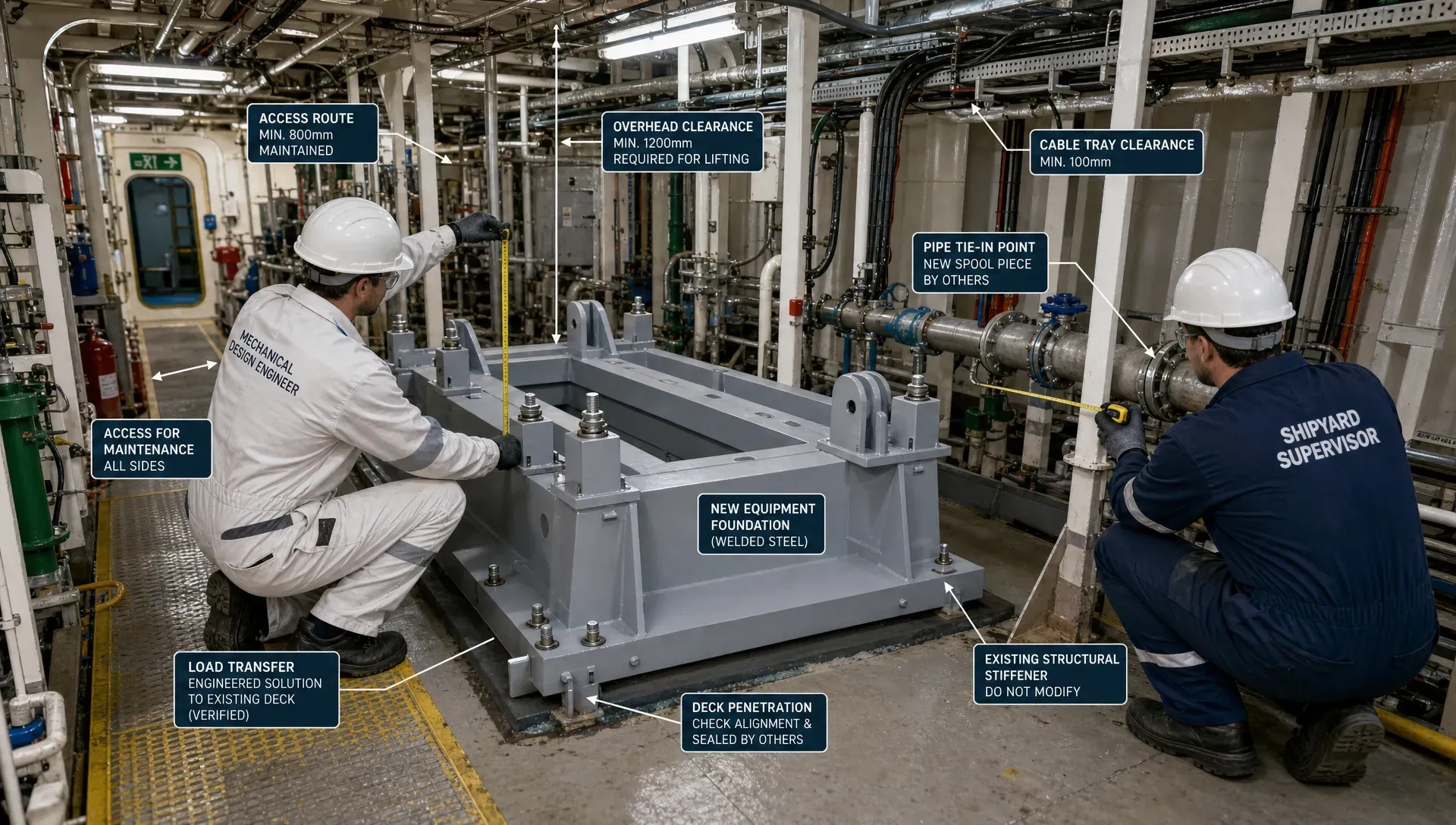
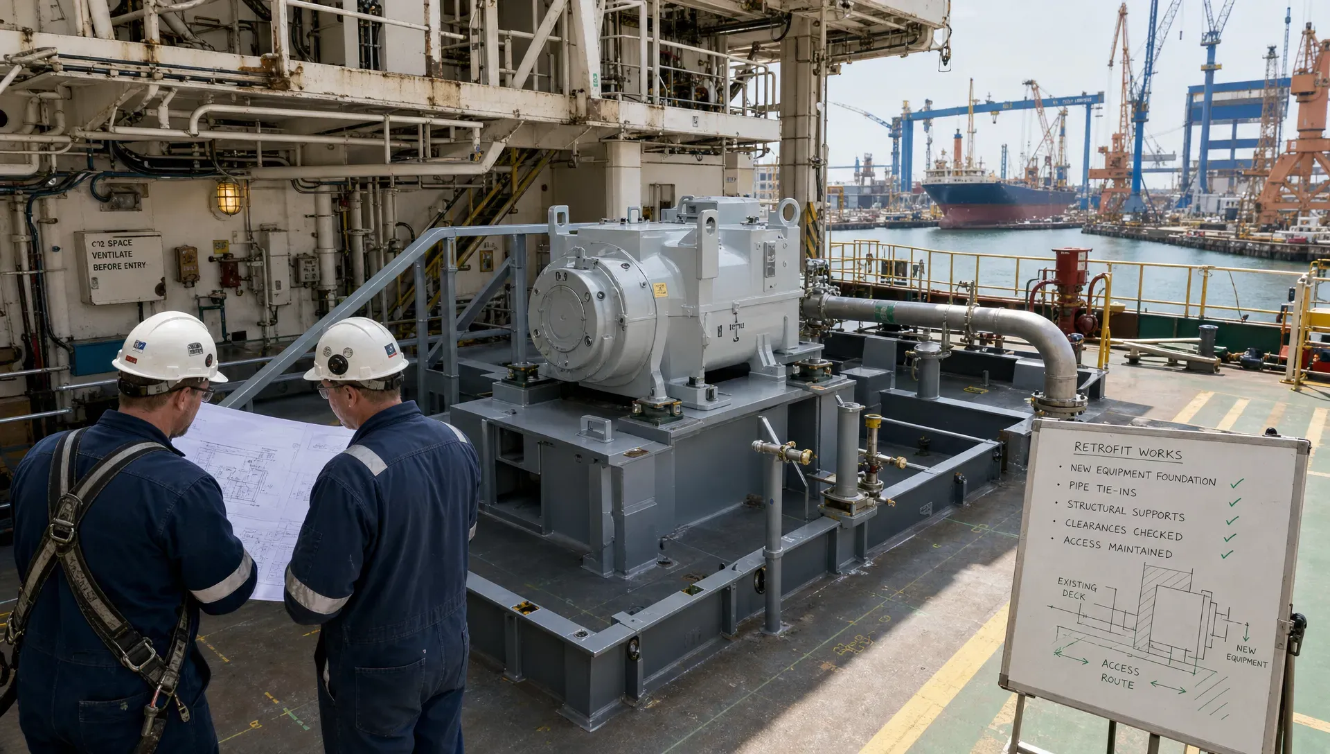
A retrofit interface is any point where a new design must physically, structurally, functionally or administratively connect with something already in place. This includes bolted connections, welded foundations, pipe tie-ins, equipment envelopes, lifting points, electrical penetrations, access routes, maintenance clearances, load paths, coating boundaries, class notations and approval documents.
The challenge is not only to identify these interfaces. It is to control them early enough that the project does not discover conflicts during prefabrication, dry dock, mobilisation or offshore execution. Late discovery is expensive because options are limited once steel is cut, vessels are booked and class review is already underway.
For a broader view of how retrofit engineering reduces schedule exposure, Fusie Engineers has also covered how vessel retrofit engineering avoids class and yard delays.
The mechanical design engineer as an interface owner
In retrofit projects, the mechanical design engineer often sits between naval architecture, structural engineering, piping, marine operations, equipment suppliers, fabrication teams and approval authorities. This position is practical rather than administrative. The engineer must understand how a design will be fabricated, installed, inspected, operated and maintained.
A strong interface owner will challenge drawings that look acceptable but are difficult to build. For example, a support bracket may be structurally adequate but impossible to weld from one side. A pipe route may avoid major clashes but block maintenance access. A foundation may spread load safely into the deck but create coating repair and hot work issues in a confined space. A bolted connection may be convenient for installation but introduce fatigue or vibration concerns if the load path is not properly understood.
The mechanical design engineer turns those issues into controlled design decisions. That requires more than CAD proficiency. It requires engineering judgement, awareness of vessel constraints, understanding of fabrication tolerances, and the discipline to document assumptions clearly for review.
Start with a controlled design basis, not a perfect model
Many retrofit teams wait for a perfect 3D model before making decisions. In practice, perfect information is rare. The better approach is to establish a controlled design basis that clearly separates verified data from assumptions.
This may include existing class drawings, yard measurements, survey reports, laser scans, equipment data sheets, loading conditions, structural capacity limits, hazardous area constraints, access routes, lifting limitations and operational requirements. The mechanical design engineer should also identify which data must be confirmed before fabrication and which assumptions can be safely carried with margin or contingency.
A useful design basis answers practical questions early:
- What existing structure is confirmed, and what still requires inspection or survey?
- Which vessel limits control the retrofit, such as deck load, stability, access, crane capacity or available power?
- Which interfaces require class, MWS, owner or yard approval?
- Which parts must be prefabricated, and which must be final fitted onboard?
- Which tolerances are acceptable, and where are adjustable connections needed?
This reduces ambiguity. It also allows project directors and lead engineers to prioritise survey work, procurement decisions and approval submissions around the interfaces that can genuinely delay the job.
Geometry is solved through envelopes, tolerances and sequence
In retrofit design, fit is not simply a matter of checking whether two objects clash in a model. The question is whether the equipment can be transported to the vessel, lifted into position, aligned, connected, inspected and later maintained.
A mechanical design engineer therefore works with design envelopes rather than only final shapes. The envelope must include installation clearance, tool access, flange bolt removal, valve operation, insulation, coating thickness, vibration movement, pipe expansion, lifting sling angles and temporary works. If the design only accounts for the final operating position, it may still fail during installation.
Tolerance management is equally important. Existing vessel structure is rarely as straight or as clean as a new model suggests. Adjustable bolted plates, slotted holes where appropriate, shim packs, field weld allowances and survey hold points can prevent minor dimensional differences from becoming major rework. However, these solutions must be engineered, not improvised. They still need proper load transfer, fatigue consideration, corrosion protection and approval traceability.
Sequence also affects geometry. A large item may fit once installed but not pass through the available route. A pipe spool may be correct but impossible to insert after a skid is landed. A support may be accessible before insulation is installed but unreachable afterwards. Good retrofit engineering checks the construction sequence against the design, not after it.
Load paths must be proven through existing structure
One of the most common retrofit mistakes is treating the new foundation, bracket or support as the main design problem. The more critical question is often what the load does after it enters the existing vessel or offshore structure.
A mechanical design engineer must work closely with structural engineers and naval architects to verify the load path into decks, bulkheads, frames, girders and local reinforcements. Static equipment weight is only the beginning. Marine and offshore retrofits may also involve accelerations from vessel motions, slamming, vibration, lifting loads, thermal expansion, fatigue, operational loads, pressure thrust, emergency cases and transport conditions.
For example, a retrofit winch, crane component, scrubber system, battery package, cable carousel support or mission equipment foundation may create local and global effects. Local stresses around welds and brackets matter, but so do underdeck stiffeners, global hull response, stability, centre of gravity and the vessel’s operational profile.
Where the existing structure is limiting, the best answer is not always to add more steel. Smart interface design may redistribute loads, change support spacing, use existing strong points, adjust equipment orientation, split modules, revise lifting points or modify installation methodology. These choices can reduce steel weight, fabrication time and approval risk without compromising safety.
Piping interfaces require early discipline
Piping is often where retrofit interfaces become visible first. A new system must connect to existing lines, tanks, pumps, valves, penetrations and supports, often in congested machinery spaces. Legacy routing may not match drawings, and small changes in spool geometry can create large consequences for installation.
The mechanical design engineer helps define nozzle positions, tie-in points, support philosophy, expansion allowances, vibration control, drainage, venting, isolation and maintainability. Pipe routing must also consider hot work restrictions, prefabrication limits, hydrotest requirements, class expectations and safe access for inspection.
This is why piping layout should not be treated as a late drafting activity. It is an interface control task. Decisions about flange orientation, support locations, valve access and spool break points affect fabrication, onboard installation and future maintenance. Fusie Engineers explores this in more detail in its article on piping layout decisions that reduce clashes and rework onboard.
Buildability is an engineering requirement
A retrofit design that cannot be fabricated efficiently is not complete. Buildability should be assessed while the design is still flexible, not after drawings are released to the yard.
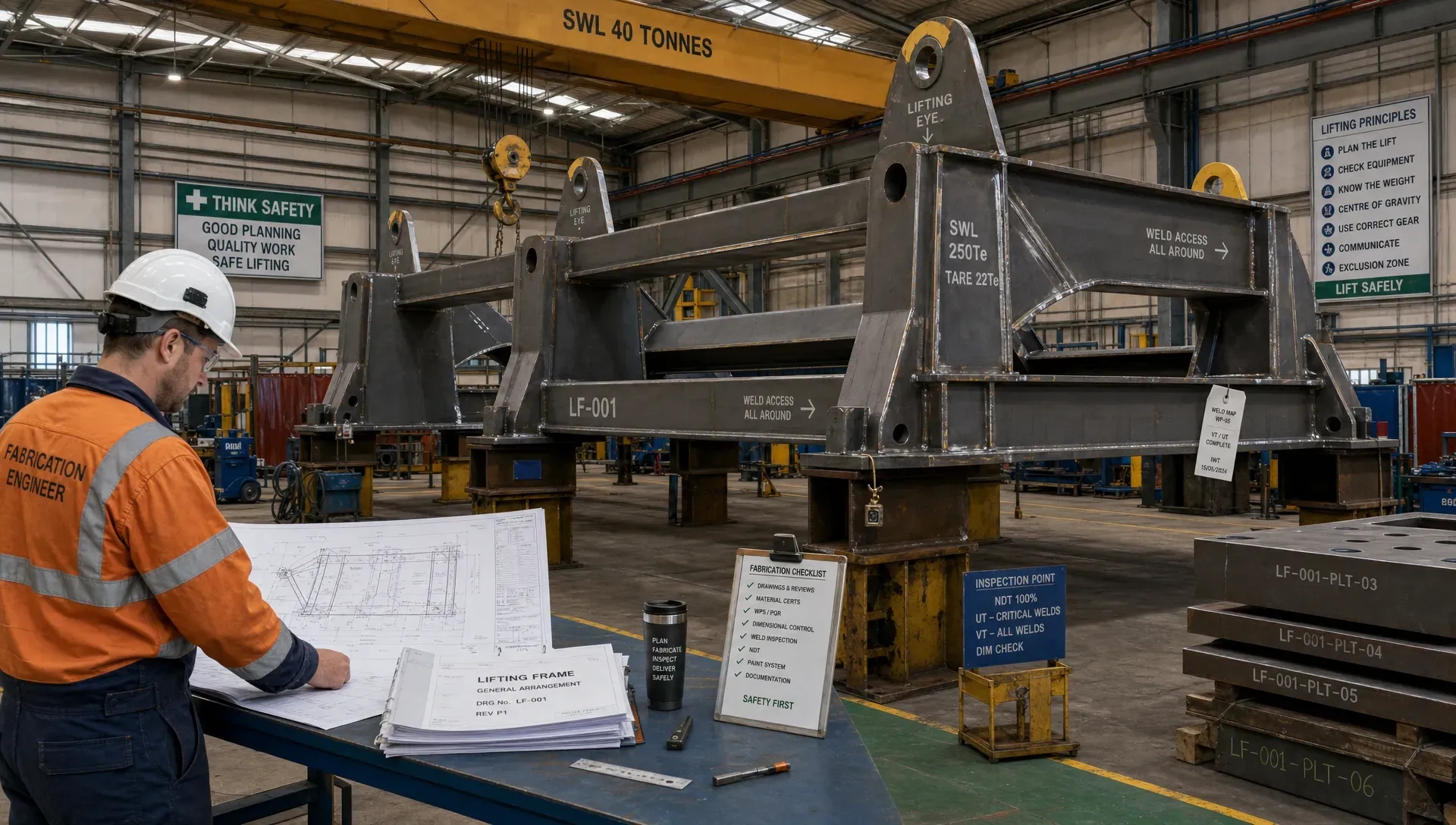
Practical buildability checks include weld access, plate availability, lifting weight, module size, coating sequence, NDT access, bolting access, temporary support requirements and whether work can be completed within the planned yard or offshore window. In marine projects, the engineer must also consider confined spaces, fire watch requirements, hazardous areas, simultaneous operations and vessel availability.
Over-engineered interfaces often create avoidable cost. Complex weld details, unnecessary stainless or exotic materials, excessive steel thickness, tight tolerances and difficult-to-reach connections can slow fabrication and increase inspection burden. A mechanical design engineer with retrofit experience will look for simpler details that still meet strength, fatigue, corrosion and approval requirements.
This is where collaboration with fabrication teams is valuable. Yard feedback can identify whether a detail is practical before it becomes a delay. However, yard convenience should not override engineering control. The best results come when fabrication input is reviewed, calculated and formally incorporated into the design.
Approval readiness depends on traceable interface decisions
Class societies, MWS reviewers and client technical authorities do not only review final drawings. They review whether the design basis, assumptions, calculations and load cases are coherent. A retrofit interface that is poorly documented can trigger questions even if the physical design is sound.
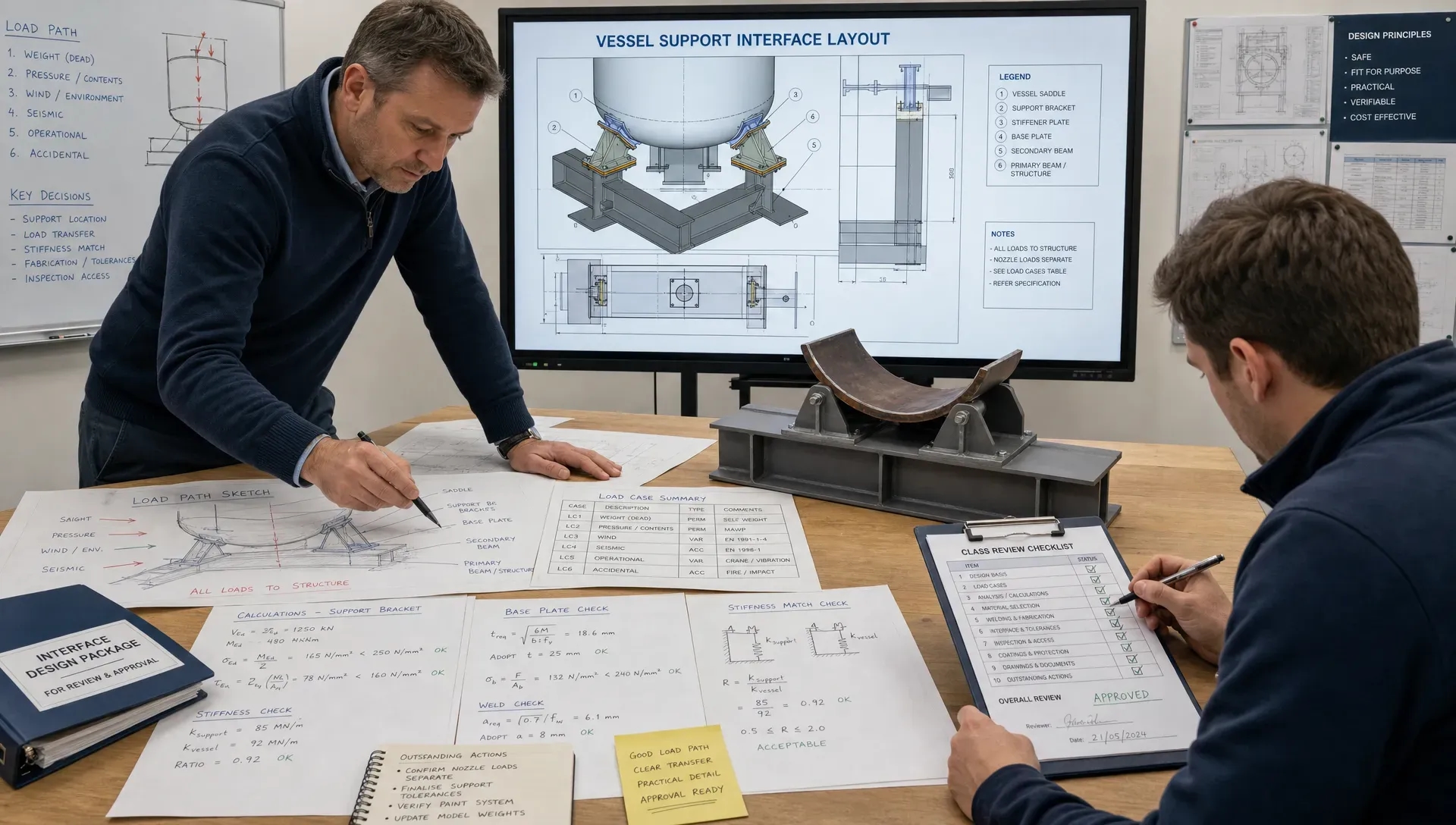
Approval-ready documentation should make it clear why the interface is safe, how the loads are transferred, which existing structure is used, what standards or rules apply, and which assumptions have been verified. Drawings, calculations, FEM outputs, equipment data, welding details, material specifications and survey records must tell the same story.
Incomplete documentation creates review loops. Review loops create schedule pressure. Schedule pressure increases the risk of field decisions being made without proper engineering closure. For projects with tight dry dock windows, mobilisation dates or offshore weather constraints, this can become a major commercial issue.
A disciplined mechanical design engineer prevents this by maintaining a clear technical audit trail. Interface registers, calculation notes, marked-up drawings, revision control and response logs are not paperwork for its own sake. They are the mechanism that keeps design, fabrication, approval and execution aligned.
Digital tools help, but they do not replace judgement
3D models, clash detection, FEM software and structured document workflows can accelerate retrofit design. They make it easier to test options, visualise congested spaces, coordinate disciplines and capture review comments. Used well, software can reduce iteration time and help stakeholders understand complex interfaces.
However, a clean model is not proof that the design is safe or buildable. Software depends on input quality, modelling assumptions and engineering interpretation. A clash-free layout can still have poor access. A foundation can pass local stress checks but overload existing structure. A drawing can look complete while omitting a survey hold point that the yard needs.
This is also true for project communication. Technical teams often focus on calculations and drawings, but complex services and scopes still need to be explained clearly to clients, stakeholders and decision-makers. Outside the engineering environment, the same principle of reducing confusion through clear structure is visible in conversion-focused website optimisation from specialists such as Sleek Web Designs, where clarity of information helps the right audience act with confidence.
For engineering workflows specifically, digital tools work best when paired with clear responsibility. Fusie Engineers discusses this balance in its article on how engineering software speeds review without losing control.
What good retrofit interface deliverables should include
The final deliverables for a retrofit interface package should support fabrication, approval and execution. They should not leave the yard or installation team guessing about critical details.
Depending on the scope, a robust package may include arrangement drawings, detailed fabrication drawings, interface registers, load calculations, FEM reports, lifting arrangements, pipe support details, equipment foundation drawings, installation notes, material specifications, weld details, inspection requirements and class or MWS response documentation.
The key is consistency. If the calculation assumes a certain load case, the drawing must show the matching arrangement. If the drawing includes an adjustable detail, the calculation must account for the final load path. If a tie-in depends on survey confirmation, the documentation must identify the hold point. If a class comment changes the design, all affected deliverables must be updated.
This consistency is what allows technical directors, engineering managers and project directors to make decisions with confidence. It also gives fabrication and site teams the information they need to execute without unnecessary requests for clarification.
How Fusie Engineers supports retrofit interface resolution
Fusie Engineers approaches retrofit interfaces with a combination of mechanical design, structural engineering, naval architecture, marine engineering, heavy lift engineering, piping design and steel detailing. That mix matters because retrofit problems rarely belong to one discipline only.
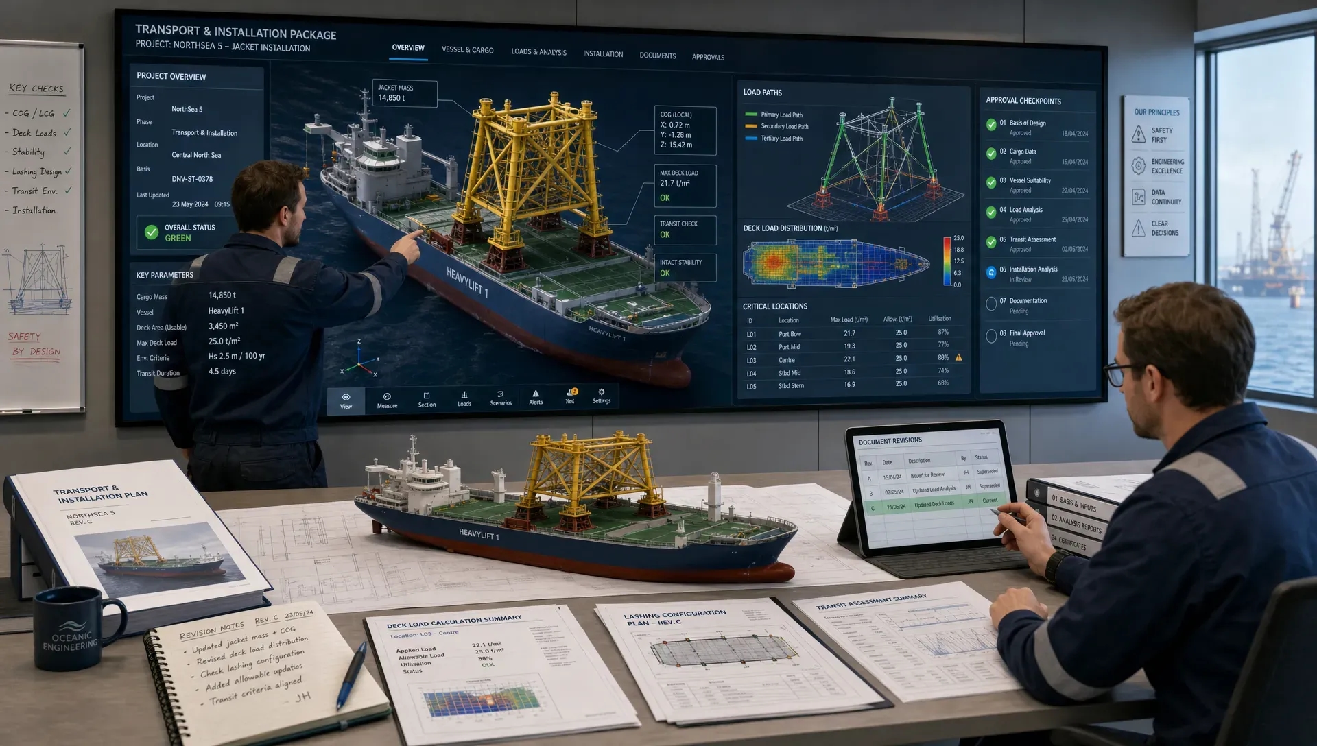
A vessel retrofit may require equipment foundations, underdeck checks, piping reroutes, lifting arrangements, stability considerations, class documentation and fabrication drawings. An offshore installation upgrade may require seafastening, grillages, temporary structures, vessel capacity checks, motion considerations and MWS approval support. A decommissioning or heavy lift scope may require custom tools, safe load transfer, clear installation procedures and practical yard execution.
The objective is not to add complexity. It is to create designs that are safe, buildable, reviewable and suited to the marine environment. That means reducing unnecessary steel where possible, avoiding difficult fabrication details, documenting assumptions clearly, and coordinating interfaces before they become site problems.
For clients working under tight schedules, this integrated approach can provide additional specialist capacity without reducing control over safety, quality or documentation. Fusie Engineers can support from concept and calculations through detailed engineering, shop drawings and operational readiness, with attention to the practical realities of class review, fabrication and offshore execution.
Frequently asked questions
What does a mechanical design engineer do in a retrofit project? A mechanical design engineer resolves the physical and functional interfaces between new equipment and existing assets. This includes foundations, supports, piping tie-ins, access, installation sequence, load transfer, maintainability and documentation for review or approval.
Why are interfaces so difficult in vessel retrofits? Vessel retrofits involve existing structure, legacy drawings, limited access, class constraints, stability limits and congested spaces. The design must work with what is already onboard, not just with an ideal model.
How early should retrofit interfaces be reviewed? Interfaces should be reviewed during concept and basic engineering, before procurement and fabrication decisions are locked in. Early checks reduce the risk of late clashes, class comments, yard delays and offshore rework.
Can software solve retrofit interface problems automatically? Software helps with modelling, clash detection, calculations and review control, but it cannot replace engineering judgement. Assumptions, survey quality, load paths, fabrication access and class requirements still need expert review.
What information is needed to start retrofit interface engineering? Useful starting inputs include existing drawings, survey data, equipment specifications, operational requirements, class rules, loading conditions, yard constraints, access routes and any known vessel limitations. If information is incomplete, the design basis should clearly record assumptions and required verification points.
Need retrofit interfaces resolved before they become yard delays?
Retrofit success depends on decisions made before steel is cut and before the vessel enters a critical yard or mobilisation window. If your project involves equipment foundations, piping tie-ins, vessel modifications, offshore installation structures, seafastening, grillages, lifting arrangements or class approval documentation, early interface control can reduce risk significantly.
Fusie Engineers supports offshore, maritime and energy projects with practical engineering that connects design quality to fabrication, approval and execution. Our team can help you define the design basis, solve critical interfaces, prepare calculation and drawing packages, and coordinate the engineering detail needed for safe, buildable retrofit work.