

Floating offshore wind farms need smarter T&I engineering
2026-07-14
Floating offshore wind is moving from pilot-scale demonstration into commercial delivery, and that changes the pressure on transport and installation teams. The turbine, floater, mooring system, dynamic cable, port, towing spread and offshore hook-up sequence are not separate work packages that can be optimised in isolation. They form one marine operation chain, and every weak interface can become a delay, a redesign or a safety exposure.
For fixed-bottom offshore wind, transport and installation (T&I) planning often centres on heavy lift vessels, jack-up availability, monopile handling, transition piece installation and offshore crane capacity. Floating offshore wind farms shift a significant part of the work into ports and sheltered waters, but they do not make installation easier. They replace some offshore lifting risk with complex floating assembly, wet tow, station keeping, mooring connection, dynamic cable pull-in and commissioning risk.
That is why smarter T&I engineering is becoming a commercial requirement, not just a technical preference. Developers, EPC contractors and marine contractors need designs that can be fabricated, towed, connected, approved and maintained with fewer surprises. In deep water, far from shore, small assumptions made during concept design can become expensive constraints during mobilisation.
The demand side also matters. Electrification, shore power, green fuels, data centres and other high-load digital activities are increasing the need for reliable electricity. Even specialist power-intensive markets such as crypto mining in UAE show how closely infrastructure decisions are tied to energy availability and cost. For floating offshore wind farms, the strategic opportunity is clear, but only if the engineering supports safe and repeatable delivery at scale.
Why floating offshore wind changes the T&I problem
A floating wind asset is a coupled system. The turbine influences floater motions. The floater geometry affects towing behaviour and port handling. The mooring pattern affects installation vessel selection and hook-up strategy. The dynamic cable arrangement affects pull-in loads, hang-off design, bend stiffener handling and offshore access. The transport condition can create load cases that are very different from the long-term operating condition.
This is why floating projects need a different planning logic from traditional bottom-fixed wind. A useful starting point is to recognise that floating wind design is not only about the final, installed asset. It is also about every temporary condition between fabrication and operation. Fusie Engineers has discussed this broader design mindset in its article on why floating wind farms demand a different design approach, and the same principle applies directly to T&I engineering.
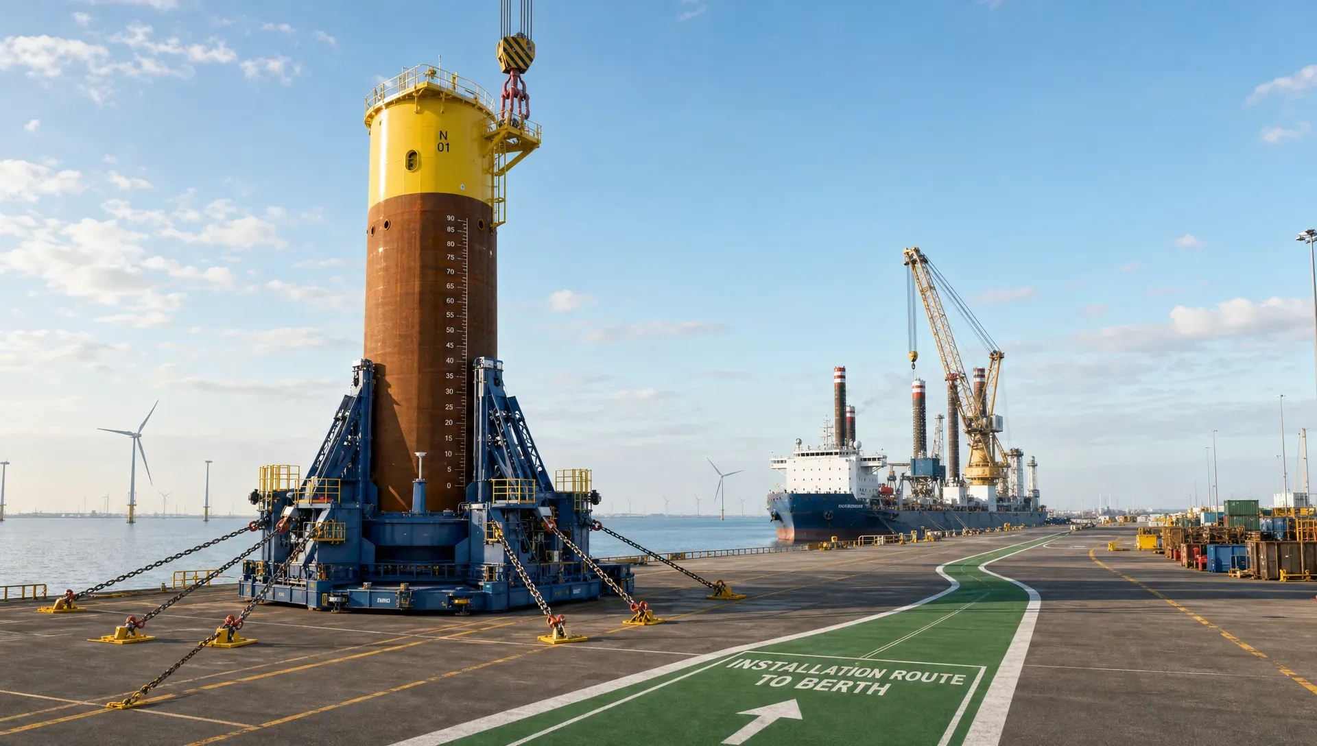
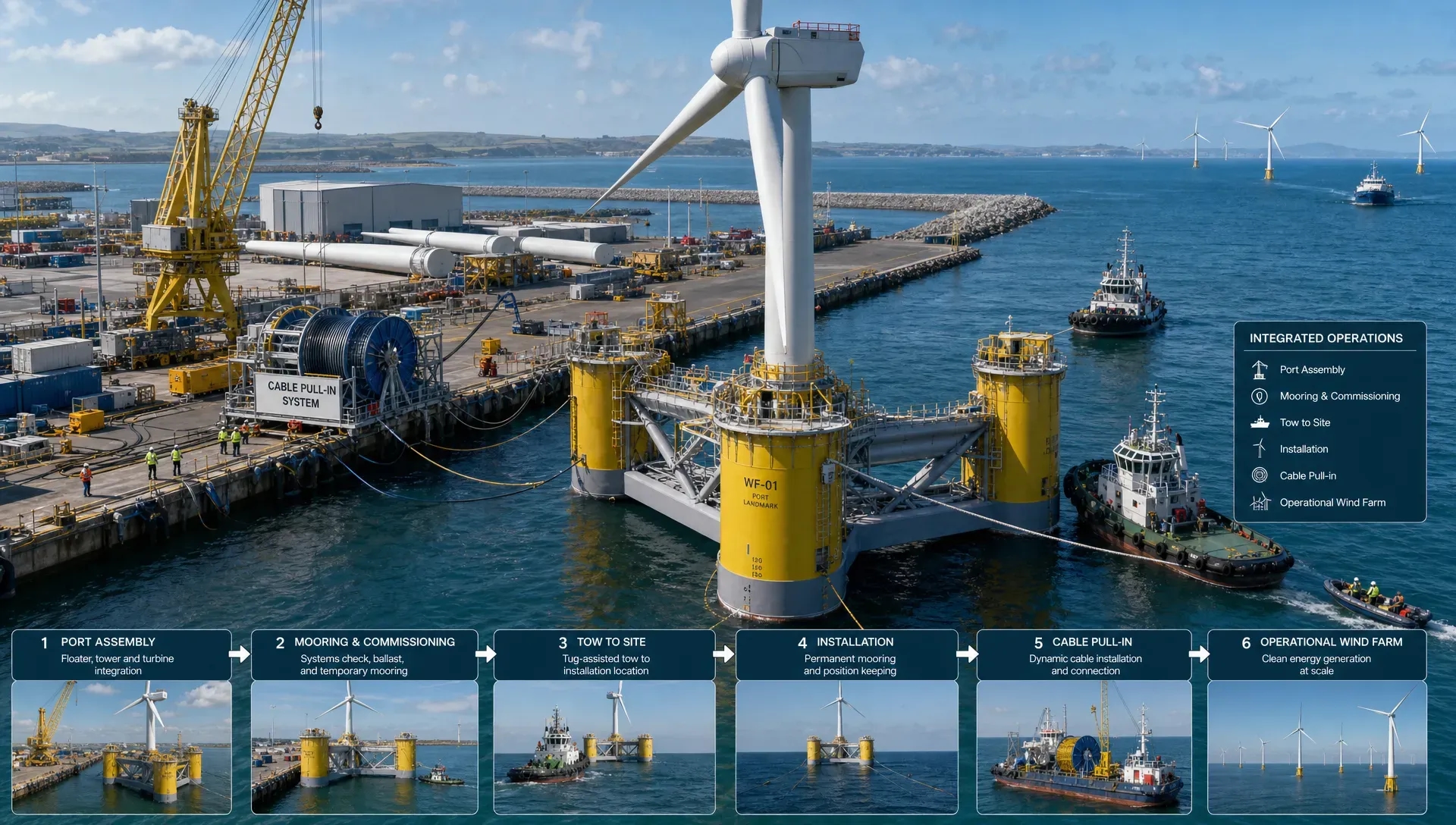
In practical terms, floating wind T&I usually involves a chain of operations such as quayside integration, load-out or float-out, wet storage, tow-out, mooring pre-lay or installation, floater hook-up, cable connection, testing and commissioning. Each step has its own allowable sea states, vessel requirements, temporary structures, interface loads and documentation needs.
The key difference is that the asset is alive in the water throughout much of the installation process. It moves, trims, heels, yaws and responds to wind, waves and current. That motion must be understood early enough to shape the structural design, not merely checked after the design is almost frozen.
The risk is not one lift, it is the interface chain
On many offshore projects, risk is often discussed around the largest lift or the most visible offshore operation. For floating offshore wind farms, that view is too narrow. A project can have no extreme single lift offshore and still face high T&I risk because the interface chain is long and dynamic.
Critical interfaces typically include:
- Quayside bearing capacity, water depth, fendering, mooring and crane reach during integration.
- Floater stability, draft, air gap and access during assembly and wet storage.
- Towing bridle geometry, tow point reinforcement, bollard pull requirements and emergency tow scenarios.
- Mooring line pre-lay tolerances, anchor positioning, line retrieval and temporary buoyancy.
- Hook-up loads, connector handling, winch capacity and safe access for offshore crews.
- Dynamic cable pull-in loads, bend radius control, hang-off support and cable protection.
- Marine warranty survey documentation, class requirements and traceable design assumptions.
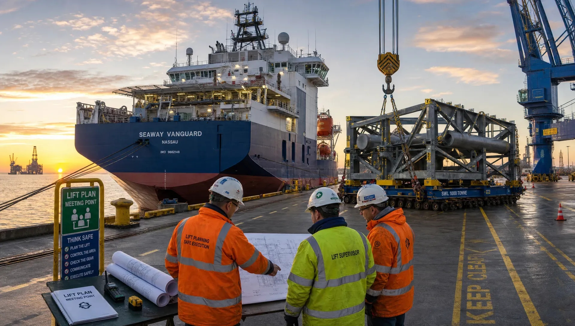
When these interfaces are treated late, engineers are forced into reactive changes. A bracket becomes larger because the load path was not aligned with the floater structure. A grillage becomes difficult to fabricate because the support points were set before weld access was considered. A vessel becomes unsuitable because deck strength, crane radius or motion response was not checked against the actual installation sequence.
Smarter T&I engineering reduces this uncertainty by bringing installation method, vessel capability, structural design and approval documentation into the same decision process.
Where standard T&I assumptions break down
Temporary conditions can govern the design
In floating wind, temporary load cases are often decisive. Tow-out, harbour manoeuvring, mooring line pickup, cable pull-in, fender contact and temporary ballast conditions can impose local loads that do not appear in the normal operating case. Padeyes, fairleads, support stools, access platforms, temporary brackets and seafastening details may control local reinforcement.
If these details are considered only during detailed engineering, the result is often heavier steel, complex welds or difficult installation access. If they are considered during concept and FEED, the same loads can often be managed through cleaner load paths, better alignment with primary structure and simpler fabrication details.
Vessel limitations must shape the method
Floating wind reduces reliance on some specialist heavy lift vessels, but it increases reliance on a wider spread of marine assets. Tugs, anchor handlers, cable-lay vessels, installation support vessels, crew transfer vessels and port equipment all influence the installation method.
The lesson from major offshore wind campaigns is that vessel integration should not be left to the mobilisation phase. Large projects such as Dogger Bank have shown how early planning, seafastening, vessel checks and repeatable procedures affect T&I certainty, a point explored in Fusie Engineers’ article on Dogger Bank wind farm lessons for transport and installation. Floating wind adds further complexity because towing, station keeping and mooring connection become central parts of the delivery model.
A technically correct structure can still be a poor T&I solution if it requires a vessel that is scarce, too costly, unavailable in the required window or difficult to approve for the operation. Engineering teams need to work backwards from real vessel capacities, deck layouts, crane curves, winch limits, bollard pull, underdeck strength and operational weather windows.
Mooring and dynamic cable operations are construction drivers
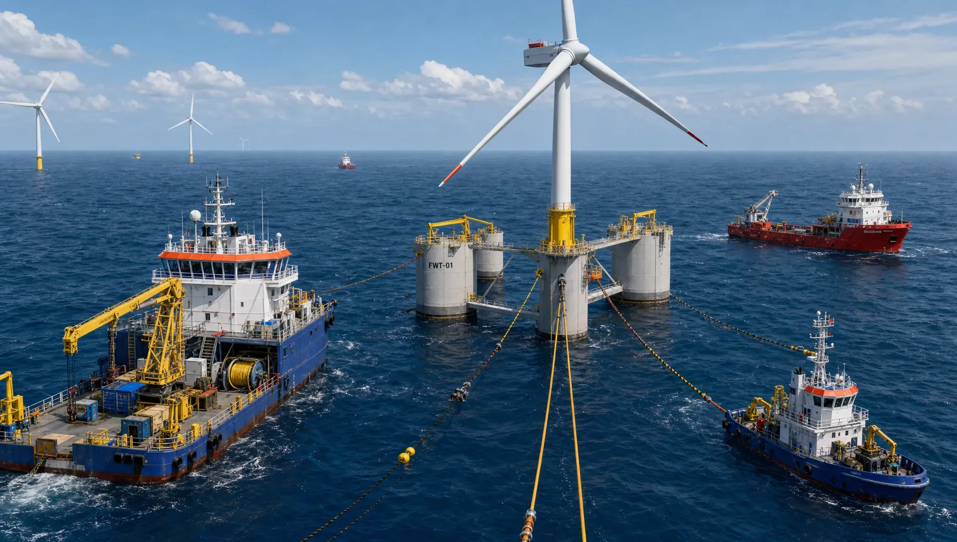
Mooring and dynamic cable systems are not only operational components. They are also installation-critical systems. Their geometry, tolerances and handling requirements influence vessel selection, installation sequence, offshore working time and contingency planning.
For example, mooring pre-lay can reduce time during final hook-up, but it creates requirements for line positioning, temporary buoyancy, retrieval and seabed management. Dynamic cable design must account for pull-in loads, hang-off structure, bend stiffener handling, fatigue-sensitive details and safe working access. If these requirements are not integrated with floater and topside design, offshore connection work can become slow, exposed and difficult to document.
What smarter T&I engineering looks like
Smarter T&I engineering starts before the final asset design is locked. It does not mean adding more analysis for its own sake. It means using the right engineering judgement early enough to prevent avoidable offshore problems.
Start with the installation philosophy
A floating offshore wind project should define its installation philosophy early, including port strategy, assembly sequence, tow-out method, mooring strategy, cable connection approach, vessel spread and weather limitations. This philosophy should become a design input, not a document produced after the main engineering choices are already made.
If a floater will be assembled at quayside, the design must reflect quay load limits, crane access, temporary mooring loads, water depth and outfitting sequence. If tow-out is performed over long distance, towing loads, fatigue during transit, emergency response and safe harbour options must be assessed. If offshore hook-up is the schedule driver, then connector access, working platforms, winch arrangement and crew safety need to be designed in from the start.
Treat temporary works as engineered assets
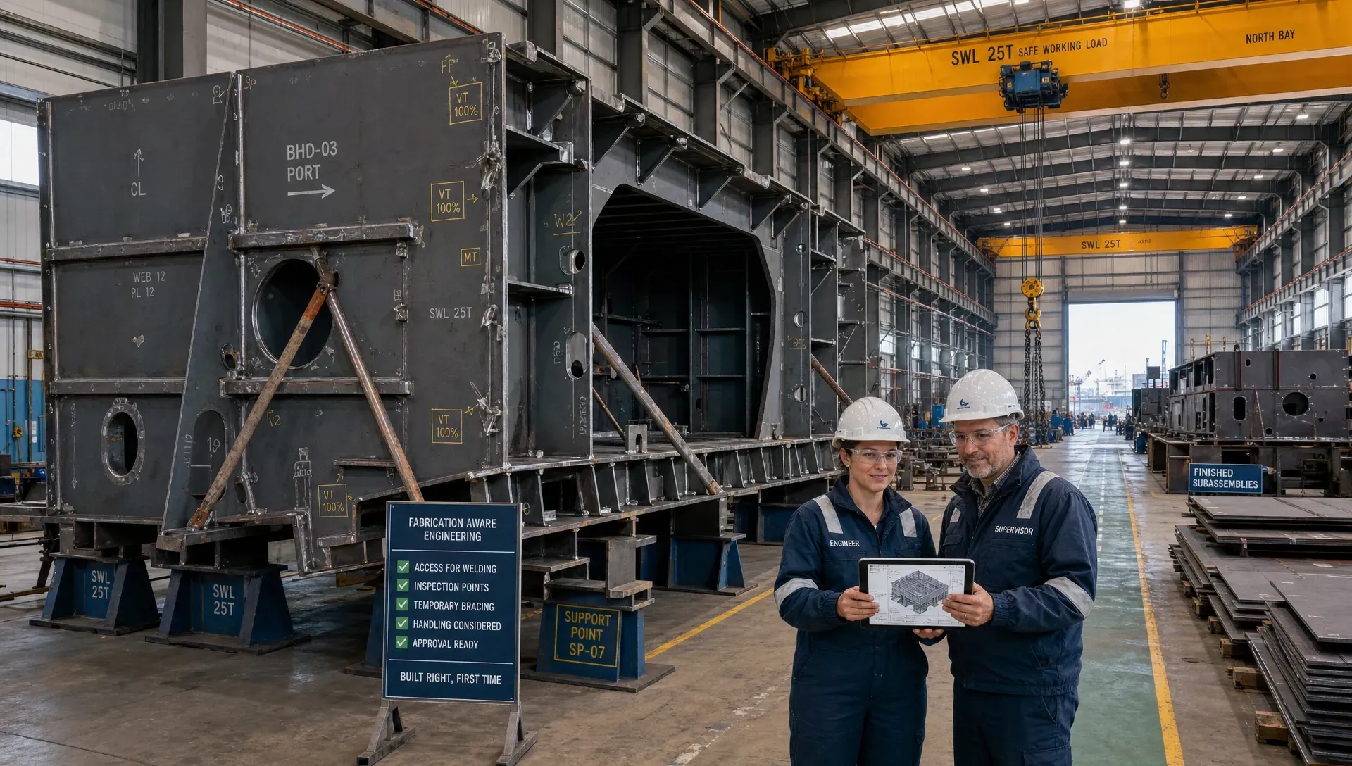
Temporary structures are sometimes viewed as secondary. In offshore T&I, they can be mission-critical. Seafastening, grillages, lifting tools, towing brackets, installation aids, access structures and temporary supports must be designed with the same discipline as permanent steel.
The best temporary works are strong enough, but not unnecessarily heavy. They use direct load paths, minimise weld volume, fit the fabrication sequence and can be inspected, installed and removed safely. Good design also considers whether temporary steel can be standardised across multiple units, reducing fabrication time and improving repeatability across a wind farm campaign.
This is where buildability has a direct cost impact. Fusie Engineers has covered the practical value of efficient load paths, fabrication sequence and clear detailing in its article on structural engineering choices that improve buildability offshore. For floating wind T&I, the same thinking helps reduce steel weight, shorten shop time and avoid difficult offshore modifications.
Use analysis to support decisions, not delay them
Floating wind T&I involves multiple analysis types, including structural calculations, FEM, lifting checks, motion response, stability checks, mooring analysis, tow analysis and local connection assessments. These analyses are valuable only when they are connected to decisions.
For example, motion analysis can inform safe tow limits and crew transfer assumptions. FEM can show whether temporary load paths are aligned with primary structure. Stability checks can confirm whether ballast states are acceptable during integration and tow-out. Mooring analysis can identify hook-up loads and vessel requirements before procurement decisions are final.
The goal is not to create a larger calculation package than necessary. The goal is to produce clear, traceable evidence that supports design choices, marine procedures and approval reviews.
Approval readiness is part of engineering, not administration
Floating offshore wind farms will often involve marine warranty surveyors, class societies, insurers, vessel owners, developers, EPC contractors and multiple fabrication yards. Approval delays can affect mobilisation, port occupancy, vessel booking and offshore weather windows.
Approval readiness depends on engineering clarity. Reviewers need to understand the design basis, applicable standards, load cases, environmental assumptions, acceptance criteria, calculation methods, drawings, procedures and change control. If those elements are inconsistent, even a technically sound design can become difficult to approve.
Strong T&I documentation normally includes:
- A clear design basis with defined codes, criteria, load combinations and environmental limits.
- Structural calculations and FEM reports for temporary and permanent load cases.
- Lifting, seafastening, towing, mooring and stability checks where applicable.
- Drawings that match the calculation assumptions and fabrication requirements.
- Marine operation procedures with hold points, weather limits and contingency actions.
- Interface registers and change records that make decisions traceable.
This is particularly important when multiple parties are working in parallel. A change to a tow bracket can affect structural reinforcement, welding sequence, coating, inspection, tow procedure and MWS review. Without disciplined document control, small changes can create late-stage conflicts.
Visualisation can reduce operational misunderstanding
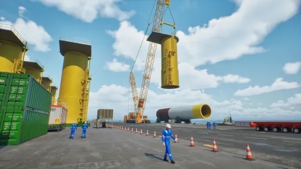
Complex floating wind operations are difficult to explain using drawings alone. Towing routes, mooring line pickup, cable pull-in, vessel positioning and exclusion zones all involve movement over time. For tenders, HAZID sessions, QHSE briefings and offshore crew preparation, technical animation and visualisation can help align stakeholders before work begins.
This is not about making a project look polished. It is about reducing misunderstanding. A clear visual sequence can show whether a vessel has room to manoeuvre, where personnel are exposed, how equipment is transferred, when loads change and which steps are critical. For project directors and marine coordinators, that clarity can improve planning discussions and reduce the risk of different teams interpreting the same procedure differently.
What engineering managers should challenge early
Before a floating wind T&I concept moves too far, engineering managers and technical directors should test whether the design team has answered the questions that usually drive later risk.
Has the installation method influenced the floater design, or is it being adapted afterwards? Are temporary load cases included in the structural model? Are tow points, mooring interfaces and cable hang-off areas aligned with primary structure? Has the vessel spread been checked against real capacities and availability? Are fabrication details practical for the selected yard? Are MWS and class review requirements understood early enough? Are drawings, calculations and procedures being developed from the same design basis?
These questions are not administrative. They determine whether the project can move from engineering to mobilisation without a costly round of redesign.
How Fusie Engineers supports smarter floating wind T&I
Fusie Engineers supports offshore wind, maritime and energy projects with structural design, heavy lift engineering, marine engineering, ship design, vessel retrofit, piping and steel detailing capability. For floating wind T&I, that combination matters because the risk is rarely confined to one discipline.
A tow arrangement may need naval architecture input, local structural reinforcement, mooring understanding and operational documentation. A cable pull-in structure may need FEM, fabrication-aware detailing, access consideration and approval-ready reporting. A temporary grillage or lifting tool may need heavy lift engineering, weld-efficient detailing and clear interface control with the vessel or floater.
Fusie Engineers focuses on practical engineering that supports fabrication, installation, maintenance and approval. Deliverables can include calculations, FEM reports, motion analyses, lifting arrangements, mooring reports, stability checks, drawings and documentation for review by MWS or class societies such as DNV, Lloyd’s Register and ABS.
For floating offshore wind farms, the value of that support is not only in producing drawings. It is in reducing uncertainty before mobilisation, aligning technical decisions with marine execution and helping project teams move toward approval with fewer late surprises.
Frequently asked questions
What makes T&I engineering for floating offshore wind farms different? Floating wind assets move throughout much of the delivery process. Tow-out, mooring hook-up, dynamic cable connection, temporary ballast, port integration and wet storage all create load cases and operational risks that must be engineered early.
When should T&I engineering start on a floating wind project? It should start during concept or FEED, before major floater, port, vessel and interface decisions are fixed. Early T&I input helps avoid designs that are technically valid but difficult, slow or costly to install.
Does floating wind remove the need for heavy lift engineering? Not entirely. Some offshore heavy lifting may reduce, but heavy lift engineering is still relevant for port assembly, component handling, temporary structures, lifting tools, load-out operations and vessel integration.
Which documents are important for MWS or class review? A clear design basis, structural calculations, FEM reports, lifting and towing checks, stability assessments, mooring or cable installation reports, fabrication drawings and marine operation procedures are typically important for review and approval.
How can smarter T&I engineering reduce project cost? It can reduce unnecessary steel, simplify fabrication, improve vessel selection, shorten offshore operations, avoid late redesign and make approval documentation more consistent. The largest savings often come from preventing delays before mobilisation.
Need installation-ready engineering for floating wind?
Floating offshore wind farms need engineering decisions that hold up in fabrication yards, ports, tow routes, offshore hook-up operations and approval reviews. If your project needs structural design, heavy lift input, marine engineering, mooring or stability support, seafastening, grillages, installation tools or clear technical documentation, Fusie Engineers can support the work from concept through detailed engineering and operational readiness.